Impact of clinker coolers
on downstream equipment
 OneStone Consulting
 OneStone Consulting
 IKN
IKN
 IKN
IKN
 FLSmidth
 Claudius Peters
 ThyssenKrupp Industrial Solutions
 A TEC
A TEC
 Martin Engineering
 Brokk
Brokk
 OneStone Consulting
![12 Dimensioning of clinker conveyors [4]](https://www.zkg-online.info/imgs/101546681_6a5eb632a5.jpg) OneStone Consulting
OneStone Consulting
 Aumund
 Aumund
 OneStone Consulting
 OneStone Consulting
 Beumer
 Scheuch
 Aumund
Clinker coolers in today’s cement pyroprocessing lines are considered to be very reliable even under kiln upset conditions. But what is the interaction of the cooler with the upstream pyroprocessing under extreme conditions and how is the downstream equipment affected? In the following article the process will be analyzed and questions answered.
1 Introduction
Modern clinker coolers require 1.7 to 2.0 Nm³/kgcli. of fresh air to cool clinker with temperatures of more than 1400 °C from the rotary kiln to outlet temperatures below 100 °C. Such clinker coolers recuperate most of the thermal energy in the clinker to provide secondary air for the burning process and tertiary air for pre-calcination achieving thermal efficiencies of about 75 % and more. Clinker coolers are also required to buffer kiln fluctuations and have no or only a minor effect on the upstream pyroprocessing system which comprises pre-heater, pre-calciner, kiln and fuel...
1 Introduction
Modern clinker coolers require 1.7 to 2.0 Nm³/kgcli. of fresh air to cool clinker with temperatures of more than 1400 °C from the rotary kiln to outlet temperatures below 100 °C. Such clinker coolers recuperate most of the thermal energy in the clinker to provide secondary air for the burning process and tertiary air for pre-calcination achieving thermal efficiencies of about 75 % and more. Clinker coolers are also required to buffer kiln fluctuations and have no or only a minor effect on the upstream pyroprocessing system which comprises pre-heater, pre-calciner, kiln and fuel burner. Some people believe this is possible, but the fact is it is not. Kiln fluctuations cannot be buffered completely, interactions with the kiln system arise and cooler performance and efficiency is constantly changing with the result that clinker end temperatures from the cooler cannot be kept constant.
2 Cooler design and process technology
Today, almost all new coolers are grate coolers, because they can provide the secondary and tertiary air for modern pyroprocessing systems with a high recuperation of the energy from the clinker. Modern clinker coolers of the latest generation are absolutely reliable. The wear of the grate plates is significantly reduced, when compared to former technology. Grate plate lifetimes of more than three years are achieved. The coolers have no or a minimum of grate riddlings. The coolers are built in modular design with throughputs of 1000 to more than 12000 t/d [1].
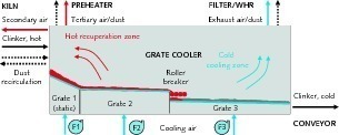
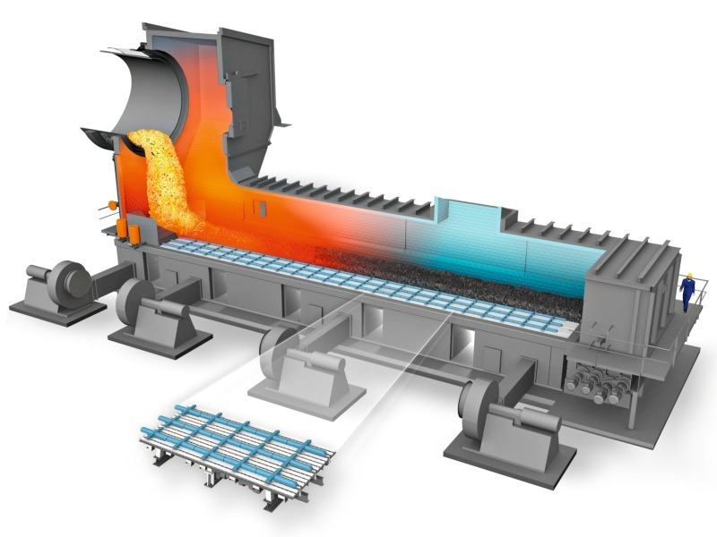
Figure 1 shows a schematic view of a modern grate cooler with three separate grates and an intermediate roller breaker as well as the major boundary conditions. Input mass flows are the clinker and clinker dust recirculating from the kiln and the cooling air, which is provided via sectional aeration chambers with separate fans. The output consists of the cold clinker, dust containing secondary, tertiary and exhaust air and dust recirculating to the kiln. The cooling air is supplied in a cross-stream to the clinker. The residence time for the clinker in the cooler under normal conditions is between 20-40 min depending on the design, clinker bed height and transport velocity of the clinker.
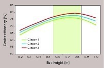
The cooling effect of the clinker is mainly affected by the clinker bed height in the cooler and the air distribution into the clinker. For each clinker quality there is an optimum average bed height, where the cooler efficiency is maximized (Fig. 2). The operating range of modern clinker coolers is with bed heights of 0.6 to 0.8 (0.9) m. If the bed heights are lower, than the residence time of the clinker in the cooler is too short to achieve sufficient heat exchange from the clinker to the cooling air. If the bed height is too high, then air blows through the clinker with insufficient distribution being achieved. Clinker bed heights vary from the cooler inlet to the outlet. On grate 1 the height mainly depends on the inclination of the grate, while on grate 2 and 3 it depends on the grate speed (stroke length and frequency of the clinker transport mechanism).
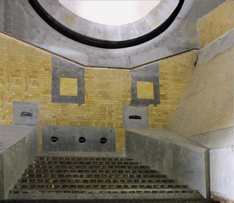
Principally, there are three different versions for modern cooler design. All versions have in common, a static first grate with no movable grates or clinker transport devices. The static grate was first introduced by IKN in 1984 as KIDS-System (Fig. 3), using a new type of grate plate (IKN Coanda effect lamellar grate plate), which ensured improved cooling of the upper surface of the grate plate and improved transport of the fines to the bed surface in combination with grate rows connected to separately aerated air-beams. The systems have been modified by other suppliers to improve clinker distribution and to eliminate “so-called” snowmen by air pulses. The fixed grate stabilizes cooler operations and results in heat savings of 20-100 kcal/kgcli. Favorable grate plate arrangements of the static grate are according to the horse show or V-shaped design to narrow fine and coarse clinker from the kiln at the landing area on the grate and to allow a uniform clinker distribution at the cooler inlet.
The most common modern cooler design is the one with movable grate plates. While conventional designs with reciprocating grates have almost disappeared from the market, pendulum suspension designs are also well accepted. Such designs are provided by IKN and CemProTec. “Pendulum” coolers are designed as single grate with a roller crusher at the end or double grates with intermediate crushing. The movable frame is suspended on a wear-free pendulum suspension consisting of spring steel strands vertically supported on steel or concrete pillars (Fig. 4). The movable frame is guided in longitudinal direction so that the system does not require any lubrication and is completely wear and maintenance free. For the grate riddlings hoppers with extraction conveyors are provided.
In 1997, FLSmidth introduced the Cross-Bar cooler, which is characterized by a static grate floor and a mechanical conveying system with thrust bars operating above the grate plates (Fig. 5). A positive effect of the cross bars is the mixing of different clinker sections. However, because the cross-bars move in the clinker they have a limited lifetime. The grate plates are horizontal to save height and no grate riddlings can occur. A similar system with transport tracks instead of cross-bars has been introduced by ThyssenKrupp Industrial Solutions with the Polytrack cooler, which also has horizontal grate plates. To convey the clinker bed the transport tracks are moved forward together and then individually moved back. The static aeration units build an aeration floor permanently filled with clinker for autogenous wear protection. The design principle is also used by Sinoma and other Chinese grate cooler suppliers.
Another mechanical transport system is the walking floor or shuttle principle which is used in clinker coolers by Claudius Peters (CP), KHD Humboldt Wedag, Fons and Sinoma (TCDRI), who licensed the Fons Technology. CP introduced the system under the synonym ETA-cooler in 2004 in a cement plant in Switzerland [2]. The ETA-cooler is completely modularized (Fig. 6), in which two different modules for the lower section of the cooler can be combined to achieve cooler capacities of 1000 to 10 000 t/d. The walking floor system achieves a longer stroke length and lower stroke frequency which has a positive effect on clinker bed height formation and mechanical wear. Furthermore the grate plate design provides autogenous surface protection. With ETA-coolers only about 7 % of the grate area has a steel/clinker contact.
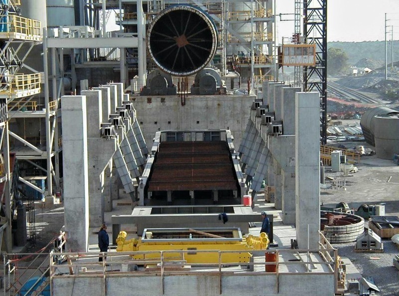
Roller crushers have become standard technology for reducing oversized clinker due to a high crushing performance, minimum dust generation and wear and no refractory damage when compared to conventional hammer crushers. The roller crusher (Fig. 7) consists of air-cooled, hydraulically or mechanically driven rollers, whose operating width completely matches the width of the cooler grate. Roller crushers offer the most benefit, when they are arranged at the end of the recuperation zone after the second grate. Due to the roller design, large lumps of up to two meters can be crushed and the crushed clinker can be effectively cooled on the final grate. If roller crushers are installed at the end of the cooler, then un-cooled hot spots of crushed clinker have to be conveyed by the downstream equipment.
3 Fluctuations in clinker input
and the cooler interaction
Kiln upset conditions have always been an important topic in the cement industry even with conventional fuels such as oil, gas and coal. With the increased usage of alternative fuels and the related problems of build-ups of chlorine, sulfur and alkali contents in the pre-heater/kiln system, material accumulation, clogging and unstable kiln operation is more frequent and more severe than ever before. On the other hand it cannot be denied that with advanced process control, kiln monitoring and inlet gas analysis kiln cycling problems have been improved. But the problems still exist and even with modern control systems stable kiln operation can not be guaranteed.
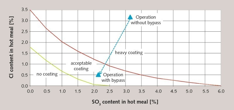
Problems start with the hot meal in the pre-heater. Chlorine and sulfur containing compounds mainly coming from the fuels are converted to HCl and SOx upon combustion. Both compounds are very reactive with a strong affinity to alkali elements. The compounds mainly condense on the incoming raw meal and are circulated back to the kiln zone where the volatile compounds re-evaporate and are transported back to the pre-heater. This is an equilibrium process which causes the condensation and accumulation of chloride and sulfate salts on the colder walls of the pre-heater cyclones, riser duct and dip tubes. If no measures are taken, the buildups eventually cause cyclone or duct blockages, which can lead to sudden incidents of hot meal flushes in the kiln and clinker cooler.
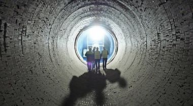
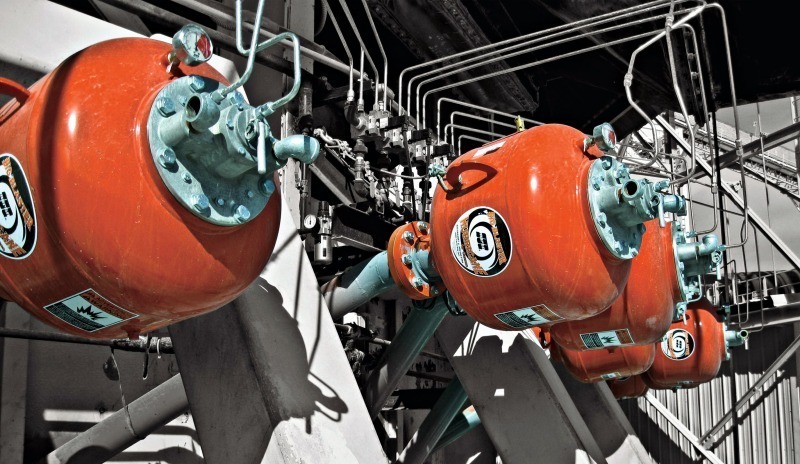
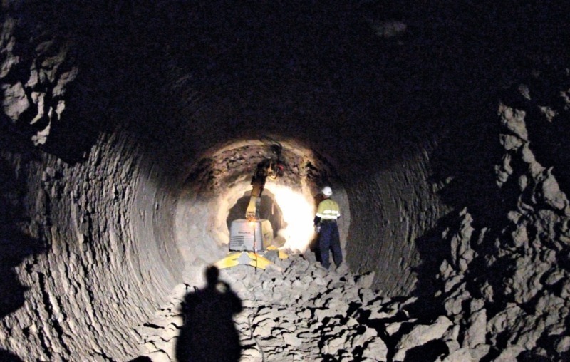
Figure 8 shows tolerable concentrations of the two major compounds chlorine and sulfur and how they can be reduced with bypass systems. There is only a small zone of relatively low chlorine and sulfur content where no coating or encrustation occurs. But with higher volumes the risk of coating increases. If the equilibrium concentrations are too high then a chlorine bypass becomes necessary to reduce the chlorine content to an acceptable level. If there are restrictions with the chorine bypass, than pre-heater cleaning measures are necessary. It is customary to clean build-up material during operation by using air cannons (Fig. 9), air or water lances, jack hammers etc. Although some plants still use manual techniques to remove buildups in the pre-heater, automated systems with air cannons have become more common.
Coatings on the refractory linings in the kiln itself are considered acceptable, because coatings are needed to safeguard the linings from thermal shocks and the high burning temperatures in the kiln. The formation of stable and desirable coating is dependent on the uniformity of the kiln feed and clinker properties, the refractory lining material and the operating regime in the kiln [3], which is largely affected by the uniformity of the fuel and burning conditions. Any changes in the kiln feed and fuel delivery rates, burnability of the kiln feed, the combustion of the fuel in the main burner or changes in secondary air for the combustion from the cooler will affect the temperature profile in the kiln and the formation of coatings.
The problem of unstable kiln operations are excessive coating and ring formations within the kiln (Fig. 10), depending on the amount and properties of flux or liquid phases at different points in the kiln. Kiln rings can form in the sintering, calcining and transition zones of the kiln. Depending on their sulfur, carbonate, spurrite or alkali induced origin they may be dense or porous and may develop slowly or in a few hours. If the ring formation is excessive the rings can collapse and can cause a flush of unburnt material into the cooler. Other phenomena are so-called snowballs, which are mostly formed with long and lazy flames that increase the temperature in the kiln and reduce the calcining zone length. Snow balls form in transition zones at temperatures around 1100 °C from low melting sulfites and get agglomerated with raw meal. As the balls reach the burning zone they get balled up with more liquid phases and can even block the kiln.
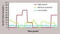
The result of unstable pre-heater and kiln conditions are fluctuating clinker inputs into the cooler (Fig. 11). Principally three different fluctuations from low to high can be observed. The low fluctuations are with stable pre-heater and kiln conditions and are easily buffered by the cooler. Coolers with higher clinker retention time might also be able to buffer medium fluctuations resulting from an unstable kiln operation, and which are about three times larger in magnitude than the stable fluctuations. High fluctuations because of kiln upset conditions and the sudden release of blockages in the pre-heater, release of kiln rings and snow balls can be about five to seven times higher in magnitude or more than in stable conditions and cannot be buffered by the cooler.
Clinker fluctuations which are much higher than the rated capacities result in interactions from the clinker cooler to the upstream kiln system and to larger clinker flows and higher clinker end temperatures for the downstream equipment. Pre-heater and kiln upset conditions increase the dust recirculation from the cooler to the kiln, generally increase secondary and tertiary air temperatures and mostly increase the secondary air flow due to increased grate speeds or cooling air volumes from the clinker cooler control. It goes without saying that this will influence the flame formation in the kiln and probably lead to another kiln operation instability necessitating the adjustment of fuel rates, kiln feed, and ID fan speed. It can take hours before new stable conditions are achieved.
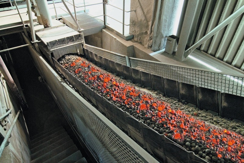
For the downstream equipment the rated parameters cannot be met. Under kiln upset conditions clinker conveyors behind the cooler are subjected to much higher clinker temperatures and higher loads. First it is important to understand that rated clinker end temperatures are average clinker temperatures, which are measured for guarantee reasons in a Dewar vessel. While clinker material is colder at the surface, in the core it is still much hotter. If the clinker from a roller crusher or hammer crusher at the end of the cooler is taken then the average temperature of the clinker with so-called hot spots will rise from the rated 100 °C to about 250 °C. Under upset conditions the rated average clinker end temperature can increase to about 350 °C, while the hot spot clinker will increase to 600 °C.
4 Downstream transports and storage
For covering kiln upset conditions, the clinker conveyors behind the cooler have to be designed for higher capacities than the rated kiln capacity. However, modern cooler designs have changed the conveyor dimensions, due to higher buffer capacities in the cooler. Fig. 12 shows the dimensions of clinker conveyors for four different plant sizes from 3000 t/d to 10000 t/d in the past and how they are different today [4]. So, before modern coolers were developed, the dimensions of the clinker conveyors was about 1.8 to 2.0 times the rated kiln capacity, with 250 t/h for 3000 t/d kilns and 750 t/h for 10000 t/d kilns. Modern coolers changed the capacities to 190 t/h for 3000 t/d kilns and 625 t/h for 10000 t/d kilns which is 1.5 times the rated capacity.
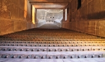
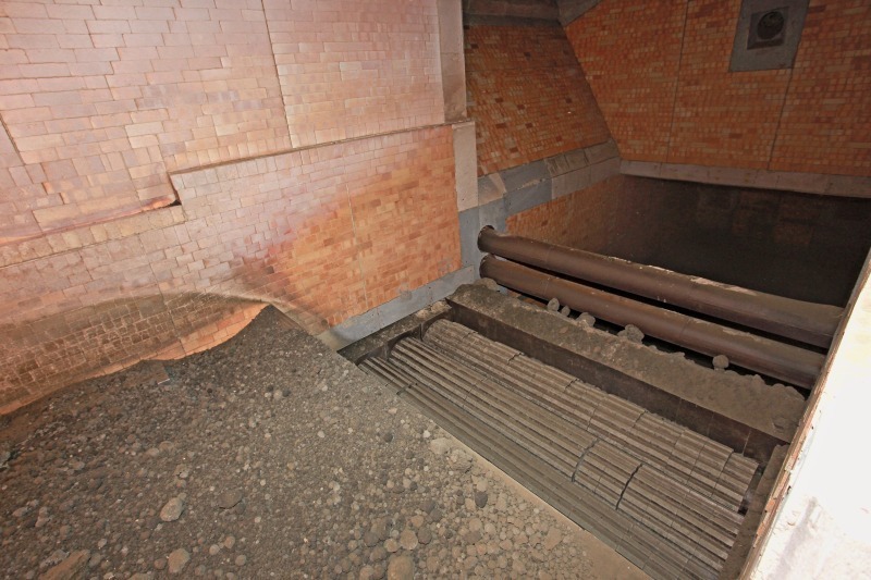
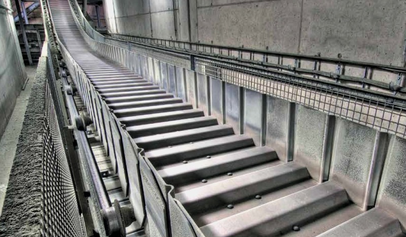
Principally, there are three different types of conveyors used for the transport of the clinker from the clinker cooler to the clinker storage facilities. The most used technology is the deep-drawn pan conveyor. Such conveyors (Fig. 13) are available up to 1000 t/h capacity and are safe for temperatures up to 700 °C. These conveyors can be used for conveying up to heights of about 75 m and inclinations of up to 30°. For larger heights of up to 100 m and inclinations of 60° and above pan conveyors with buckets are used. Hybrid conveyors of the belt apron type with a temperature resistance of 600 °C design are another option, but they have not achieved a high market penetration yet. High temperature belt conveyors are tested from time to time for the clinker transport behind the cooler, but up to now have not met with any commercial success.
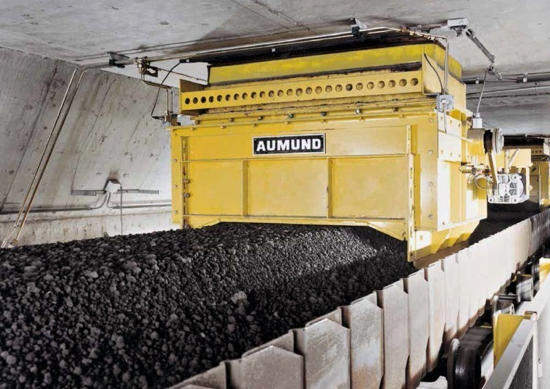
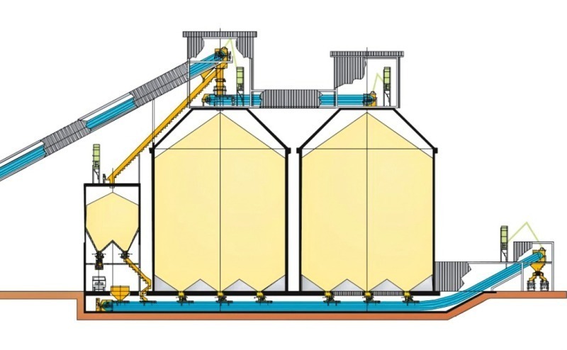
Today, adequate clinker storage capacities are designed to accept a clinker production of two to three weeks to provide enough buffer for unscheduled kiln shutdowns or for annual shutdowns. Safety provisions have been reduced in the last few years due to optimized annual shutdown management and the combination of clinker and cement storage capacities to overcome lengthy periods without clinker production. However, with limited clinker capacities such cases increase, where clinker from the clinker cooler is conveyed without any buffer time to the cement mills. Consequently the clinker conveyors from the clinker storage silos (Fig. 14) to the cement mills can be subjected to high clinker end temperatures from the cooler.
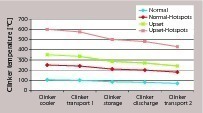
Figure 15 gives an approximation of typical clinker temperatures from the clinker cooler to the downstream equipment, including the pan conveyor behind the cooler, the clinker storage, clinker discharge from the storage and clinker transport to the mills.
Under normal conditions and clinker end temperatures of 105 °C (85 °C + 20 °C ambient temperature) behind the cooler, the clinker will cool down to about 70 °C. This temperature is not high enough for slag grinding applications, and for such applications, which are in the trend, clinker end temperatures of about 180 to 200 °C behind the cooler are specified. Such temperatures can be achieved when a roller breaker is located at the end of the cooler and hot-spots are taken into account. Problems occur in upset conditions, when clinker temperatures over 350 °C are not decreased by much more than 100 °C during storage and conveying.
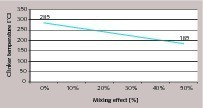
One very important aspect is the temperature mixing effect of the clinker storage (Fig. 16). The mixing effect depends on the clinker storage design and how many discharge tunnels are located below the storage and operated simultaneously.
So for example if there is clinker stored with 85 °C temperature in normal conditions and with 285 °C in upset conditions, then with a 50 % mixing effect an average clinker temperature of 185 °C will result. Under practical conditions mixing effects of 20-30 % are more realistic. Realistic average temperatures from the clinker storage depend on the number of upsets, the frequency of higher clinker end temperatures and the time period that they are stored. The more upsets recorded the higher the average clinker temperature.
With an, assumed, better performance of modern clinker coolers, belt conveyors are increasingly used to transport the clinker from the clinker storage facilities to the cement mills (Fig. 17), and intermediate silos for the mills. The belt conveyors offer lower installation costs when compared to steel pan conveyors, but the maintenance costs are usually significantly higher, so that life cycle costs mostly favor pan conveyors, especially when the costs for filters in belt conveyor installations are included in the cost comparison. High temperature resistant belt conveyors are constantly improving but cost advantages might come down to zero. There are enough cases where belt conveyors are doing an excellent job, but there are also cases where belt conveyors had to be replaced by conventional pan conveyors.
5 Exhaust air and WHR systems
In modern grate coolers with efficiencies of 75 % about 45 % to 50 % of the cooling air is used for combustion (secondary and tertiary air), while 50–55 % is exhaust air. So with specific cooling air quantities of 1.7 to 2.0 Nm³/kgcli. about 0.85 to 1.1 Nm³/kgcli. is exhaust air. Under normal conditions the exhaust air has temperatures of 250 ° to 350 °C, which can increase during kiln upset conditions to 400 ° to 500 °C. Normal dust concentrations in the cooler exhaust air are in a range of 30 to 90 g/Nm³, under upset conditions dust concentrations can increase to more than 200 g/Nm³.
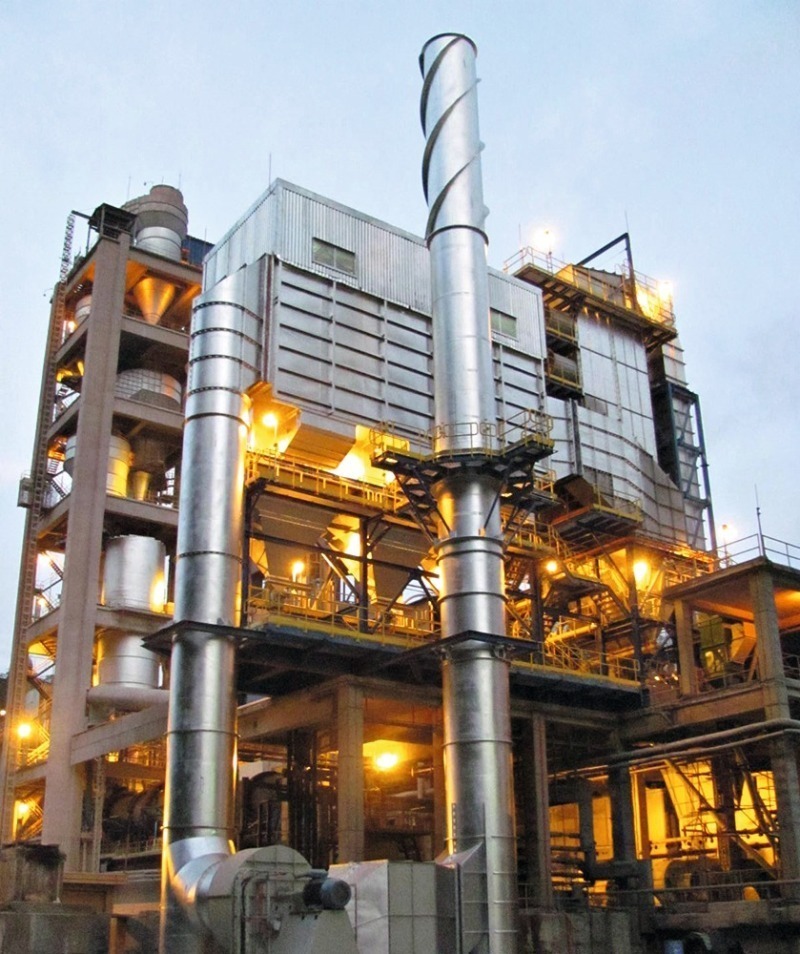
Due to higher emission standards, clinker cooler de-dusting systems have changed significantly in the last few years [5]. Instead of electrostatic precipitators bag filters are used nowadays in spite of difficulties with the variable flow rates in normal and upset conditions and the high abrasiveness and loads of the clinker dust. To cope with the clinker cooler exhaust gas conditions, cyclones and air/air heat exchangers are installed upstream of the filters (Fig 18). The cyclones reduce the dust concentrations of up to 75 g/Nm³ by around 70 % for the heat exchanger. The heat exchanger cools down the exhaust air to temperatures of below 150 ° and 180 °C, which are acceptable for polyester or Nomex filter bags. To reduce temperature peaks, water spraying devices or controllable fresh air dampers are frequently installed.
With higher cooler efficiencies the potential for waste heat recovery (WHR) from the clinker cooler decreases. However this offers potential for ORC (Organic Rankine Cycle) and Kalina cycles, where organic working mediums or binary water-ammonia mixtures are used as the working medium instead of water which is used in conventional steam cycles [6]. These working medias have a significantly lower evaporation point than water, which corresponds to higher vapour pressures and enables a higher degree of efficiency in the lower temperature range of clinker cooler exhaust temperatures below 300 °C, than is possible with water-steam circuits. Consequently the technology is offered by an increasing number of suppliers. With standard containerized WHR plants there is an opportunity to generate about 0.65 to 0.7 MW of electricity from 4.5 MW of waste heat from the cooler.
6 Outlook
In the last few years rated clinker end temperatures have decreased from 105 °C, to 85 °C and 65 °C (plus ambient temperature). But with an increasing demand for mixed cements and the grinding of slag cements the trend has changed and clinker end temperatures in cooler specifications significantly increased. Cement producers asked the cooler suppliers how the clinker end temperatures could be increased. In some specifications, now clinker end temperatures of 180 ° to 200 °C are required.
With modern clinker coolers there has also been a trend to so-called stripped down equipment solutions. Stripped down means that design capacities of clinker conveyors are reduced to 125 % instead of 150 % or 200 %. Such solutions are usually selected when clinker coolers are upgraded and bottlenecks in the operation of clinker coolers are removed. There is no need for new clinker conveyors to be installed as long as there is a 125 % safety margin in the conveyor capacity. Furthermore standby conveyors behind the clinker cooler are no longer foreseen in plant layouts to the extent it was some years before.
Überschrift Bezahlschranke (EN)
tab ZKG KOMBI EN
This is a trial offer for programming testing only. It does not entitle you to a valid subscription and is intended purely for testing purposes. Please do not follow this process.
This is a trial offer for programming testing only. It does not entitle you to a valid subscription and is intended purely for testing purposes. Please do not follow this process.
tab ZKG KOMBI Study test
This is a trial offer for programming testing only. It does not entitle you to a valid subscription and is intended purely for testing purposes. Please do not follow this process.
This is a trial offer for programming testing only. It does not entitle you to a valid subscription and is intended purely for testing purposes. Please do not follow this process.