Clinker cooling in the course of time
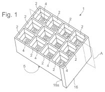
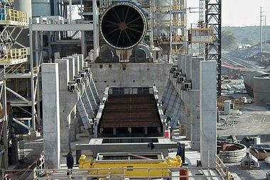
Cooling takes place in the clinker bed. The grate cooler has to provide just for a favourable air flow and clinker handling (Fig. 1). This perception alone is not sufficient to obtain orders resulting in a good reference and for the conquest of the market. It is essential to offer something new.
Grate resistance was a first idea in which the uniformly designed grate, not the clinker bed, was to determine the air flow under all the circumstances that the rotary kiln creates for the cooler. The consequence was the “open grate area OGA” as a portion of the openings in the grate with regard to...
Cooling takes place in the clinker bed. The grate cooler has to provide just for a favourable air flow and clinker handling (Fig. 1). This perception alone is not sufficient to obtain orders resulting in a good reference and for the conquest of the market. It is essential to offer something new.
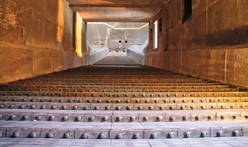
Grate resistance was a first idea in which the uniformly designed grate, not the clinker bed, was to determine the air flow under all the circumstances that the rotary kiln creates for the cooler. The consequence was the “open grate area OGA” as a portion of the openings in the grate with regard to the overall grate surface. At the outset, all grate coolers were reciprocating grates with rows of perforated plates arranged across on grate support beams. The velocity of the air escaping from a hole or a gap in the grate surface could be measured with a mini-anemometer. When the undisturbed flow against the chamber concerned was calculated at 1 m/s and when the air jets out of grate openings measured 10 m/s, then 10 % of open grate area had accelerated the air flow correspondingly. It quickly became clear that good grates had an open surface of 8 % and troublesome grates had open surfaces of 15 %. Figure 2 shows a grate surface from the past with an open area of more than 15 % compared to the grate of an IKN pendulum cooler with 2.5 % of open grate area and a considerably higher grate resistance.
In 1985 we came to an agreement with Professor Jeschar and Dr. Wager, both from Clausthal University [1], to use an open grate surface of 2.5 %, which was a quarter of the habitual 10 %, with the aim of being able to aerate a bed of double the height and to save half of the grate surface. Still, nothing could be sold as yet.
Reverse flow in the clinker bed was the next idea. Narrowing the open grate area to a quarter meant to quadruple the velocity of the air jets leaving the grate and entering the clinker bed. For a uniformly aerated bed and not taking into account the thermal expansion of the air an air velocity within the voids of the bulk clinker of 1.5 to 2 m/s could be expected. Entering air jets of 40 m/s had to result in a considerable reverse flow, which in turn would entrain clinker fines and cause wear of the grate surface by hot sandblasting.
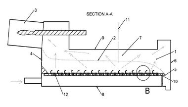
Via the Californian foundry engineer Futer Henry Coanda from Romania presented the solution: Inclined slots. The air jets entering vertically are diverted horizontally and are rendered harmless. They are even useful for handling the fine portion, which is difficult for any scraper conveyor including the reciprocating grate cooler (Fig. 3).
The question was how to generate inclined slots in the foundry process? When casting grate plates with vertical holes, these are kept free by removable plugs. With thin and even inclined slots this was no longer possible, although a patent suggested exactly this, which was very troublesome from the legal point of view. After all, IKN obtained patents according to which slots were formed between separately cast parts. A German foundry spared no efforts to achieve this, and finally sales could now go ahead, at first in Germany (Fig. 4).
There were many discussions and compliments, such as, “That’s just fantastic, at last something new”, but only a few minutes later from the other side of the table, “Where has it proved successful?” At Dyckerhoff AG it was put into practical terms. During a works manager conference, I had 15 minutes to present the solution. Then the Hellbach works in Beckum, that had been completely dismantled in the meantime, was chosen to install a slotted plate from IKN in the cold part of the grate on a trial basis. The works manager at Hellbach could not refuse to accept this because he had not taken part in the conference. It was scheduled that the plant should continue production for a further three months only.
What should be thought about a single slotted plate at the cold end of the grate under these circumstances? Arranged next to perforated plates with a low resistance, no air passage could be expected. The slots would fill up with fines and after three months the whole affair would be forgotten. IKN had to convert at least the surface of an entire grate chamber. However, that was asking too much. The compromise was a grate row, later called air beam, covered with slotted plates, where no material could pass, including a corresponding fan.
The works manager agreed to install an air beam in place of the last grate row in front of the crusher and sent me downstairs to the workshop to clarify the details. Whilst going there, five air beams formed in my mind. The workshop manager - I have forgotten his name in spite of his merits - referred me to the refractory ramp at the grate inlet, which he had always wanted to be aerated. The first clinker inlet distribution was the result of these coincidences. We called it KIDS for “clinker inlet distribution system” with many children (kids) in mind (Fig. 5).
The inlet aeration and the distribution effect leveraged the new grate plate. This was a great step. However, nothing was sold as yet. After three months there was the danger of losing the reference. Fortunately, the Geseke works located nearby, which also belonged to the Dyckerhoff Group, could be interested in this.
The first sales negotiation took place. In the meantime another supplier of grate coolers had reacted and had developed individually aerated grate plates. A plate box was welded in the right angle between the supporting surface and the front of each grate plate. It was equipped with a one-inch air connection. A first grate in France had been equipped with dozens of these plates. There were photos on the negotiating table showing the plates, the plate boxes and numerous hoses leading to the grate plates. Also from Hellbach photographs of the IKN air beams were on the table.
The technical part of the negotiation was held with the technical works manager, who called for the director to finalize the negotiation commercially. The director, who has known me for a long time, came to the table, took several of the photographs lying astray and praised me for my contribution to the technical development and cost reduction. However, for a firm of worldwide reputation like the other supplier - and now he had the photos of Hellbach in his hands – it does not take long to present a professional solution, and the decision had to be taken in favour of this solution. He had fixed is decision so firmly that he had to stick to it despite of the mistake in the suppliers. Once again coincidence played a role.
For safety reasons and provision of spare parts, the conversion of the grate cooler at Geseke had to be identical with that of Hellbach. We succeeded in doing so and from spring 1985 we had the reference longed-for. The VDZ (German Cement Works Association) had carried out process measurements and Dr. Ruhland [2] as well as Dr. Matthée [3] reported on operational experience. Meanwhile, during 26 years of operation no grate plates have been replaced. Already after 5 years IKN had advertised the reliability. However, a clever visitor from France had his reasons, granted, to make fun of it: Tiens, elle n’est pas belle et elle ne veut pas mourir (she is not beautiful - he referred to the clinker distribution – and she doesn’t want to die either).
Only with later projects clinker distribution was achieved forming an equally deep clinker bed of equally permeability for the air saving further equipment for air distribution. The increasing throughputs required wider and wider grates. Milestones in the KIDS development were grate widths of 5.6 m for 9000 t/d, then of 6.8 m for 11 000 t/d and up to 7.2 m for an output of 13 000 t/d. Today all manufacturers of any type of grate cooler offer clinker distribution by means of fixed inclined grates. They were the key to the renaissance of the grate coolers instead of the rotary coolers (Fig. 6).
The original business idea was to equip half of the 2000 operating grate coolers with KIDS through the years, i.e. 1000 units. However, after about 75 conversions it could be seen that with each project further dialogue partners on the customers’ side were added and, because of the intervention in their daily responsibility for the entire plant, it was necessary to stay personally in long term contact with them. IKN could not further increase the number of dialogue partners, but had to offer more technology to less market participants. Thus, the complete grate cooler was the business target.
The precision for control of the open grate surface of the entire grate was less an idea than a working program for the years to come. Each new grate should be better than the previous one. This concerned the reduction of the unintended thrust and side gaps of the grate surface, and this irrespective of wear, applied load and thermal expansion. The suspension of the movable structure on pendulums and fixture of grate plates yielding to thermal expansion were essential technical solutions (Fig. 7). From the IKN point of view there is no reason that the movable parts of grate coolers should not be as durable and free from clinker throughfall like the KIDS.
At the outset of the development there were grate coolers in the USA, in which the air compartments and dust hoppers were brick-lined and the supporting structure was of stainless steel. Right from the start, IKN designed without such safety measures and cast grate support beams as well as sideboards up to the level of the bed. At the outset the blades of the grate elements were fixed in cast boxes. Today they are of tilted steel plate. Thus, only the blades of the top layer are of heat-resistant casting. With increasing control of the clinker distribution and of the transfer of the clinker bed from KIDS to the driven grate - after 6 months of operation no charred paper of a cement bag was found at this point – it is conceivable that a hardened metallic grate surface will be sufficient in the future. Absent high temperatures and fines wear due to clinker transport is negligible. Considering the increasing electricity prices, protecting the grate surface with clinker fixed in boxes should not be considered economic in the long run.
As mentioned above, cooling takes place in the clinker bed. Thus, the question is: What is the best clinker bed? In the meantime the specialists at IKN have been observing more than 500 grate plants delivered and discover again and again: The best clinker bed consists of clinker granules resting on each other due to their own weight and between which there are fines that are carried to the bed surface due to a finely dispersed aeration. There thee fines form a gently fluidized bed. As opposed to this, formerly the grates with perforated plates released the fines to the under grate. To separate the fines to the bed surface will only be achieved up to a certain, optimum depth of the clinker bed, which, like the size distribution, is difficult to forecast for new plants. IKN does not specify the bed depth for the customers but helps them to cautiously approach the optimum (Fig. 8).
Mechanically sheared beds or beds wavering due to aeration cannot be the optimum. A comparison with the solutions of competitors is made difficult because deviations from the optimum have only a minor effect on the recuperation of the cooler due to the error compensating temperature radiation in the hot zone. However, in the central and cold part of the grate the effect of optimum beds becomes clear. On the tide of the energetic utilization of the waste heat of the grates, the “cold” recuperation will become important in connection with high temperature of the waste air. New designs of the grate elements are in the course of being prepared for this.
They say that old people prefer to look back rather than ahead. Perhaps it could also be said that they have a clear conception of larger periods of time including the future and that they recognize developments. Thanks to ZKG for publication of these visions.
Überschrift Bezahlschranke (EN)
tab ZKG KOMBI EN
This is a trial offer for programming testing only. It does not entitle you to a valid subscription and is intended purely for testing purposes. Please do not follow this process.
This is a trial offer for programming testing only. It does not entitle you to a valid subscription and is intended purely for testing purposes. Please do not follow this process.
tab ZKG KOMBI Study test
This is a trial offer for programming testing only. It does not entitle you to a valid subscription and is intended purely for testing purposes. Please do not follow this process.
This is a trial offer for programming testing only. It does not entitle you to a valid subscription and is intended purely for testing purposes. Please do not follow this process.