Latest trends in clinker cooling
 (Source/Quelle: OneStone)
 (Source/Quelle: (Claudius Peters)
 (Source/Quelle: IKN)
 (Source/Quelle: FLSmidth)
 (Source/Quelle: Polysius)
 (Source/Quelle: CemProTec)
 (Source/Quelle: FLSmidth)
 (Source/Quelle: OneStone)
 (Source/Quelle: OneStone)
 (Source/Quelle: Thermoteknix)
 (Source/Quelle: VDZ)
 (Source/Quelle: VDZ)
 (Source/Quelle: VDZ, OneStone)
 (Source/Quelle: IKN)
 (Source/Quelle: Claudius Peters)
 (Source/Quelle: FLSmidth)
 (Source/Quelle: KHD)
 (Source/Quelle: Polysius)
 (Source/Quelle: Polysius)
![20 Market shares for new coolers 2007–2008 [12]](https://www.zkg-online.info/imgs/101528452_2bfe6e8196.jpg) (Source/Quelle: OneStone)
(Source/Quelle: OneStone)
 (Source/Quelle: Claudius Peters)
![22 Market shares for cooler conversions 2007–2008 [12]](https://www.zkg-online.info/imgs/101528377_51061219d6.jpg)
Summary: In the course of the rapid cooler development in recent years, new generations of grate coolers have come onto the market. In fact, it has meanwhile become difficult to keep track of the current cooler generation. However, despite the new market introductions, no great improvements have been made with regard to cooler efficiency and the cooling principle. This report provides an overview of the main equipment developments of recent years and relates them to the process technological background. It discusses the important parameters determining the efficiency of a clinker cooler and shows how the solutions and market shares of the individual plant engineers differ.
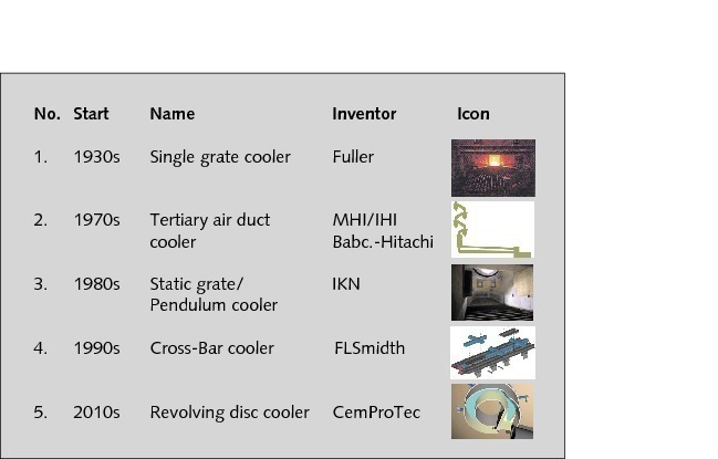
When cooler vendors bring a modified grate cooler onto the market, they like to present it as a new cooler generation. Customers generally see a new cooler generation in connection with fundamental improvements in process technological and mechanical upgrades. So how far are these customer expectations met by the characteristics and operating results of new coolers? Figure 1 shows the grate cooler generations introduced so far. This only takes account of developments that represent a decisive advancement of existing systems. The first grate cooler generation was introduced by...
When cooler vendors bring a modified grate cooler onto the market, they like to present it as a new cooler generation. Customers generally see a new cooler generation in connection with fundamental improvements in process technological and mechanical upgrades. So how far are these customer expectations met by the characteristics and operating results of new coolers? Figure 1 shows the grate cooler generations introduced so far. This only takes account of developments that represent a decisive advancement of existing systems. The first grate cooler generation was introduced by Fuller (now FLSmidth) in the 1930s. With the RDC Cooler (RDC = Revolving Disc Cooler) from CemProTec we can today possibly speak of the 5th cooler generation.
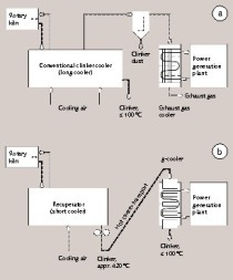
The 1st cooler generation from leading manufacturers was on the market until the end of the 1960s. This involved conventional single-grate coolers with alternating rows of static and moving grate plates. Such coolers were operated with grate surface loadings of 20 tpd/m2 active grate area and specific cooling air volumes of 2.7 to 3.3 kg/kgcli.. With the improvement of cooler efficiencies and the appearance of kiln systems equipped with calciners and drawing tertiary air from the clinker cooler, the 2nd generation of reciprocating grate coolers developed [1], which were serious competitors for the hitherto widely used planetary coolers. In addition to tertiary air withdrawn from the clinker cooler (Fig. 2) and the associated efficiency improvements, other concepts introduced were the combi-cooler, with several cooler grates, the multi-stage cooler, with intermediate crushing of the partially-cooled clinker, and concepts with recuperator/g-coolers [2-4].
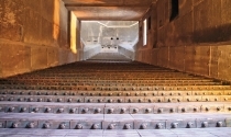
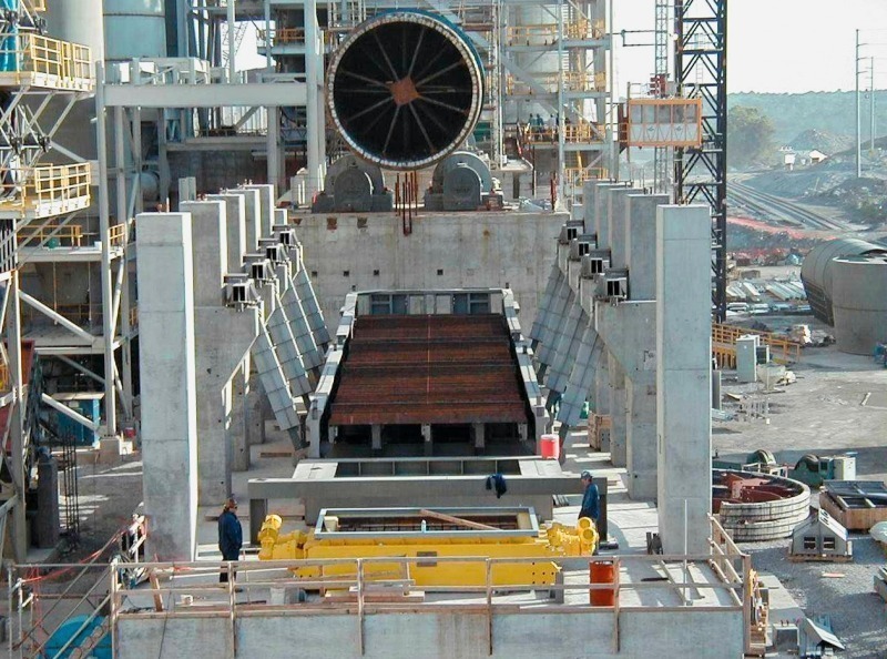
The 3rd generation of clinker coolers came in the 1980s due to the increasing competition between manufacturers of grate coolers and the higher demands imposed on cooler efficiencies, throughput rates and cooler availability. IKN (Ingenieurbüro Kühlerbau Neustadt) made the first move, bringing the static inlet grate onto the market under the designation KIDS (Clinker Inlet Distribution System). This utilized a new type of grate plate (IKN Coanda effect lamellar grate plate), which ensured improved cooling of the upper surface of the grate plates and simultaneously distributed the air to individual rows of grates (air-bar effect) [5]. IKN integrated this principle into their “Pendulum” coolers (Fig. 3), a new type of grate cooler equipped with a completely new low-wear oscillating frame bearing assembly. The specific electrical power consumption for the grate drive was significantly reduced. A similar principle was utilized for the PGC cooler from CemProTec and the CSS cooler from Claudius Peters.
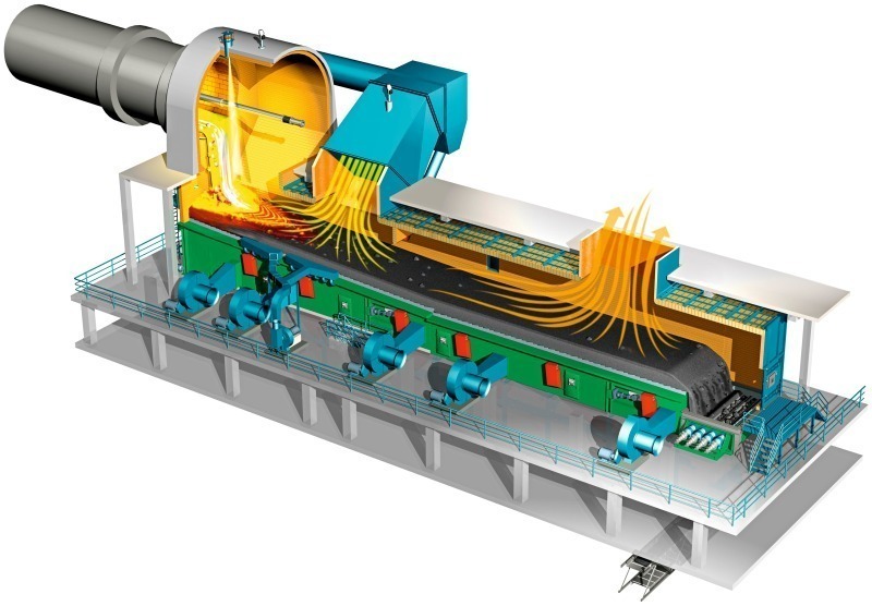
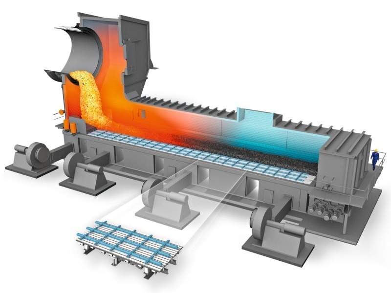
The 4th grate cooler generation can really no longer be called reciprocating grate coolers. At the end of the 1990s, FLSmidth introduced the Cross-Bar cooler, which had a completely static grate floor with moving thrust bars operating above the grate plates to convey the clinker through the cooler (Fig. 4). Other developments were also introduced, such as mechanical air stream controllers for regulating the aeration and air distribution in the bed of clinker [6], and individual thrust bar modules enabling separate forward and return stroke speeds over the length of the grate. Polysius introduced the Polytrack (Fig. 5), a grate cooler operating on a similar principle with the clinker moved through the cooler by a thrust system operating separately from the grate floor. A different grate modification was provided by Claudius Peters with the Eta cooler and by KHD Humboldt Wedag with the Pyrofloor cooler equipped with a non-static aeration and conveyance floor designed according to the “walking floor” concept.
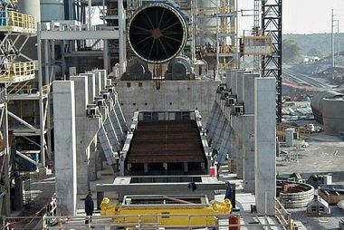
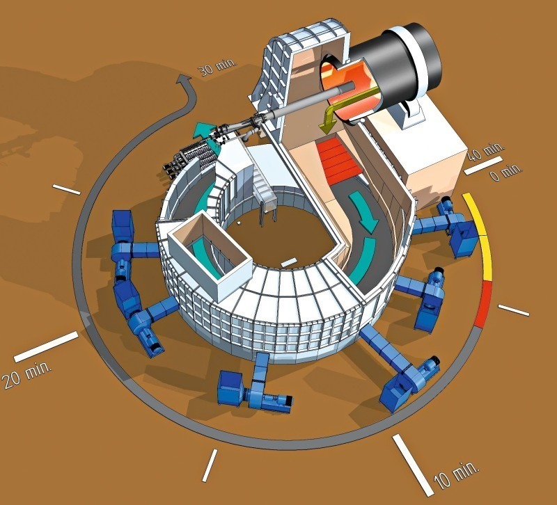
The current 5th generation of coolers was introduced by CemProTec, who have set new standards for the conveyance efficiency of a clinker cooler. Their clinker cooler operates according to the “revolving disc” principle (Fig. 6). The principle of a revolving heat exchanger has been in use for many years in the steel industry. In a clinker cooler the travelling grate is replaced by a revolving disc which takes about 30 minutes for one complete rotation. It achieves 100 % conveyance efficiency. A static grate is installed at the cooler inlet, which is positioned at a 90° angle to the kiln outlet. This eliminates problems caused by different centre lines of kiln and clinker cooler and by segregation of the clinker particle sizes over the width of the cooler. However, this new type of cooler has not yet been proven in full-scale operation, so the first results are being awaited with intense interest by the industry.
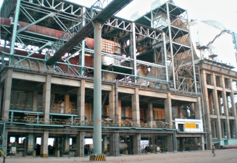
Today, coolers of the 3rd and 4th generations are the “non-plus-ultra” in the cement industry. The static inlet grate has proven so effective that it has become standard equipment for new coolers from all manufacturers (Fig. 7). Practically no differences can be ascertained in the cooler efficiencies, availability rates or wear of the different design concepts that are on offer. A few Chinese manufacturers regard clinker coolers with a static inlet grate as 4th generation coolers, even if they do not have the other characteristics of the coolers shown here. There are also some manufacturers who declare simple modifications to the static inlet grate to be a new cooler generation.
A grate cooler can be regarded as a simple heat exchanger through which the clinker passes across or counter to the cooling air flow and a direct heat transfer takes place between the hot clinker and the cold cooling air. The desired maximum recuperation of the heat from the clinker cooler for use in the kiln system for specific quantities of secondary and tertiary air demands that these combustion air quantities drawn from the cooler have the highest possible temperature. To obtain maximum possible clinker cooling using the lowest possible cooling air volumes, it is necessary for the clinker to remain in the cooler for a particular length of time and for the cooler to achieve the best possible distribution of clinker and cooling air. While the clinker retention time in the cooler is determined by the grate surface loading and clinker bed depth and thus by the transportation speed of the clinker, the factors decisively influencing the distribution of clinker and air are the machine design, the properties of the clinker and the depth of the clinker bed.
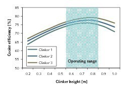
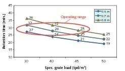
Figure 8 shows the qualitative relationship between the bed height and the cooler efficiency for different clinker qualities. With clinkers 2 and 3, the highest cooler efficiency is achieved at a bed height of 0.8 m. With clinker 1, the highest cooler efficiency is obtained at a bed height of 0.7 m, and problems due to air blowthroughs can be expected if the bed height is either lower or higher. For this reason, critical bed heights and corresponding bed pressure losses are also defined [5]. The influence of different clinker bed heights and grate surface loadings on the retention times in a 3,000 tpd clinker cooler is shown in Figure 9. The higher the grate surface loading, the lower the retention time at a given bed height in the cooler. Conversely, the retention time of the clinker in the cooler rises in line with increasing bed height. In the depicted range of bed heights, practicable retention times of around 30 minutes can most easily be achieved with grate surface loadings of 40 to 45 tpd/m2.
In order to optimize and to assess a clinker cooler, a degree of efficiency is defined. This can be derived in the easiest way as follows [7]:
h = (A – B) / A · 100 %(1)
with h = cooler efficiency in %
A = heat intake quantity of the clinker cooler
B = heat losses of the clinker cooler
The heat intake quantity is the amount of heat brought out of the kiln by the clinker and is also the relevant quantity of heat from the cooling air. The overall heat losses result from the heat losses in the cooler vent air, the wall heat losses of the clinker cooler and the remaining thermal energy of the cooled-down clinker. The difference between the heat intake quantity A and the heat losses B is by definition the recuperated quantity of heat C for the kiln. The corresponding result from equation 1 for the cooler recuperation efficiency:
hrec = C / A · 100 %(2)
hrec = (heat quantity in secondary air + heat quantity in tertiary air)(3)
(heat quantity in the hot clinker + relevant heat quantity in cooling air)
The relevant heat quantity in the cooling air results from the enthalpy of the cooling air multiplied by the ratio of recuperated combustion air volume to the total cooling air volume. Although equation 3 is relatively easy to apply, in practice a number of different calculation regulations are used for the cooler efficiency. These particularly attempt to take the dust recirculation and dust mass flows of the cooler into consideration. It should be noted in this connection that the dust concentrations are determined by the limit values set by the cement plant operator for the gas velocity at the kiln hood and the velocity of the cooler vent air. Instead of the heat quantity of the clinker discharged from the kiln, sometimes the enthalpy difference between hot clinker and cool clinker is used in the denominator of equation 3 [8]. Other approaches also include the quantities of heat used for drying purposes (combined grinding and drying) or for Waste Heat Recovery (WHR) as gained heat.
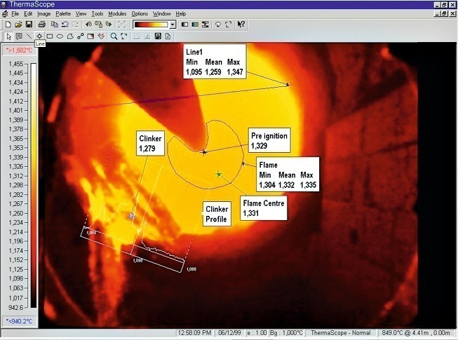
The more complicated the calculation rules for the cooler efficiency, the clearer it becomes that precise mass flow, volume flow and temperature measurements are needed for producing a mass and energy balance for a clinker cooler. Possibly, analyses of the combustion gases will also be necessary. The problem is that there are no sharp balance limits between the cooler and the kiln that can be used for these measurements. Furthermore, the measured values are obtained at greatly differing points in time due to the considerable fluctuations in the hot clinker discharged from the kiln (Fig. 10), and its temporal mass flow, temperature and granulometry. The dust quantity flows and dust temperatures are practically unmeasurable and it is also virtually impossible to determine how and at what temperatures the combustion air volumes split up. The temperatures of the hot and cool clinker can only be approximately measured.
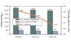
Often the opinion is expressed that mechanical factors are mainly responsible for determining the efficiency of a clinker cooler. Model calculations of the Verband der Deutschen Zementindustrie (Association of German Cement Producers) [9] for the heat requirement of kiln systems can be used as an example to show the great influence of marginal system conditions. Figure 11 shows the most important calculation values for three cooler sizes with clinker capacities between 1,500 and 5,000 tpd with the respectively best specific heat requirement, quantity of heat from the cooler vent air and specific cooling air volumes. For the reference calculation for a 3,000 tpd cooler a cooler efficiency of 73 % is calculated and the specific grate surface loading is 39 tpd/m2, i.e. an active grate area of 76.9 m2 is assumed for this cooler. The grate width loading is 857 tpd/m and the average clinker bed height is 797 mm, i.e. approximately 0.8 m. The clinker inlet and outlet temperatures are constant, at 1437 °C and 115 °C.
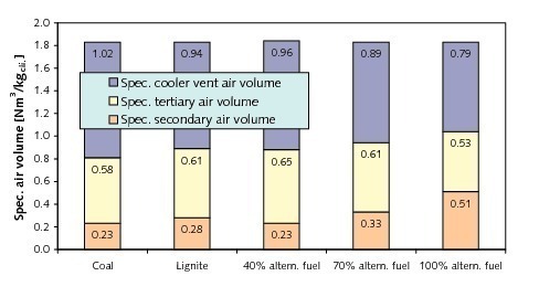
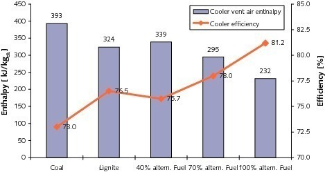
Figure 12 illustrates how different fuels cause changes in the combustion air and vent air volumes of the reference calculation even if the cooling air volume is constant at 1.83 Nm3/kgcli.. The hard coal used as reference fuel in the calculation (27 MJ/kg) is first substituted by lignite (22 MJ/kg) and then by a virtual alternative fuel (20 MJ/kg for the kiln firing system, 16 MJ/kg for the calciner firing system) at a substitution ratio of 40 %, 70 % and finally 100 %. Corresponding to the increasing amounts of alternative fuel, the required combustion air volumes drawn from the clinker cooler increase while the vent air volumes decrease. The effect of the model calculations on the cooler efficiency according to equation 1 and equation 3 is shown in Figure 13. Due to the changeover from hard coal to lignite the cooler efficiency rises from 73 % to 76.5 %. If 100 % alternative fuel is used, the cooler efficiency increases to 81.2 %.
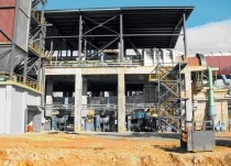
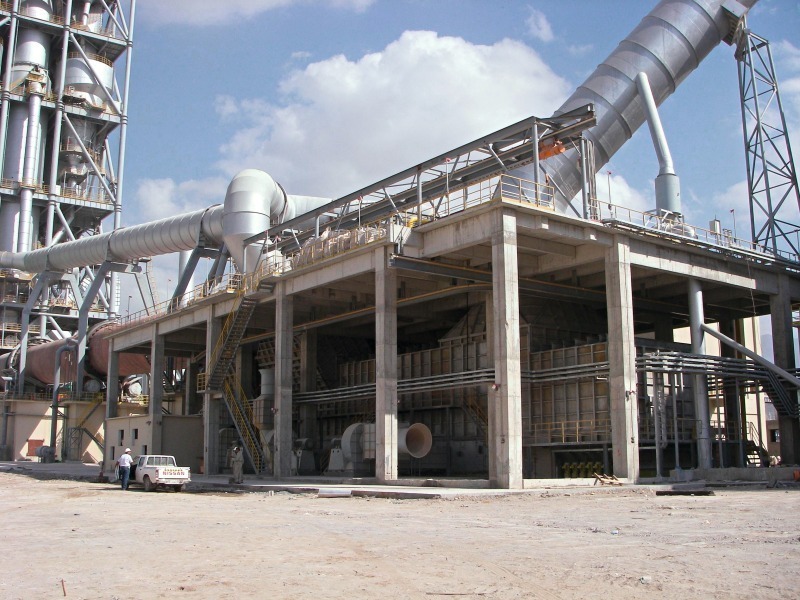
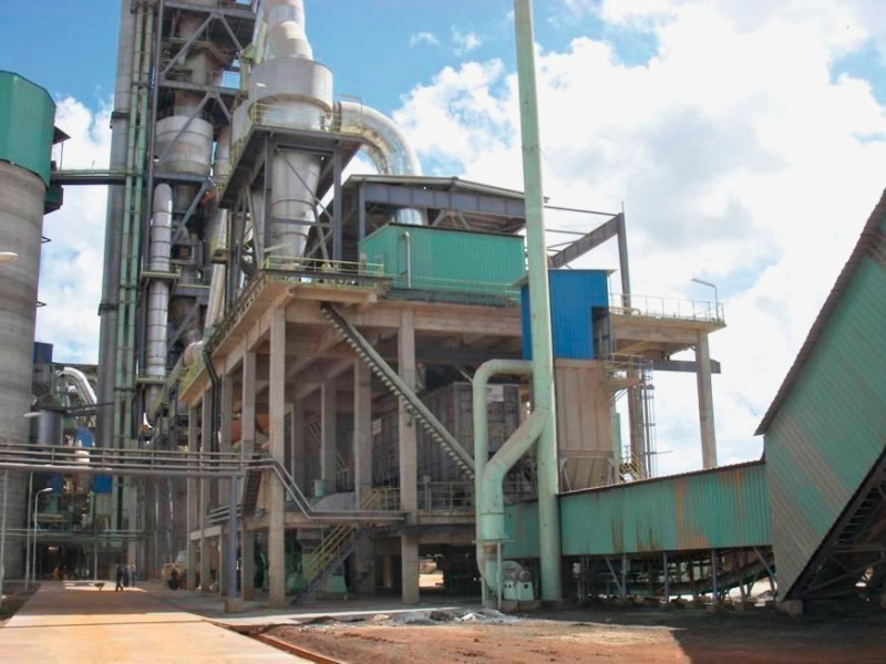
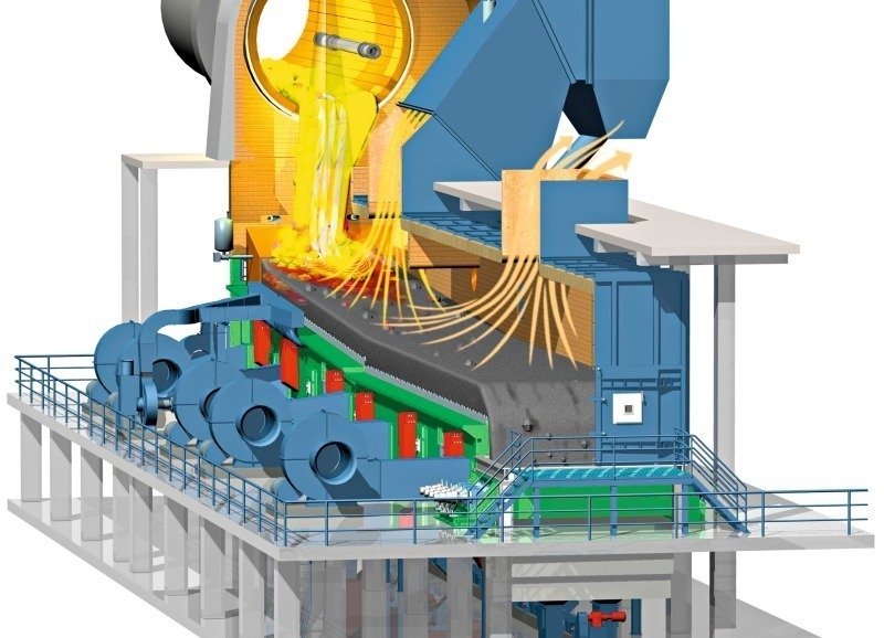
Nowadays, modern clinker coolers of the 3rd and 4th generations (Figs. 14 & 15) are designed to permit the maximum possible range of application in the maximum possible throughput range. The cooler efficiency is no longer taken as the sole optimization target. As made plain by the preceding section, a standardized consideration of combustion air volumes and ultimate clinker temperatures should actually be used for comparing the efficiency of grate coolers. On the other hand, the properties of individual clinkers differ and it is therefore just as valid to consider individual cases and marginal conditions. Cement producers usually specify numerous process parameters, such as specific grate area loading and grate width loading for a cooler project. The desired ultimate clinker temperature and the installed specific cooling air capacity are also specified.
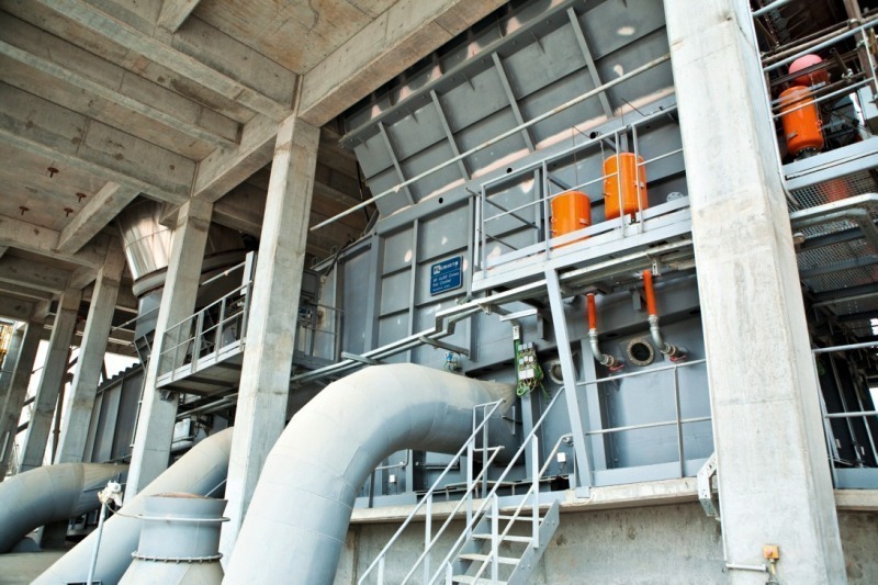
High cooler efficiency rates can only be achieved at specified combustion air volume and ultimate clinker temperature values if the specific cooling air volumes are minimized. In order to achieve high cooler efficiencies in practice coolers are operated with specific air volumes of 1.6 to 1.7 Nm3/kgcli.. However, specific air volumes of 1.8 to 1.9 Nm3/kgcli. are more usual. The installed air volumes are higher by a factor of 0.4–0.5 Nm3/kgcli.. If the plant owner has made no particular specification, the specific grate surface loadings are generally 45 tpd/m2. Higher values of 50–55 tpd/m2, which were used in cooler designs some years ago, have not really been generally accepted. In the meantime, adequate experience has also been gained with very large coolers for clinker throughput rates > 10 000 tpd (Figs. 16 & 17) [10]. In many such cases larger safety factors are incorporated than those resulting from model calculations. This is a consequence of the poorer clinker and air distribution in large coolers.
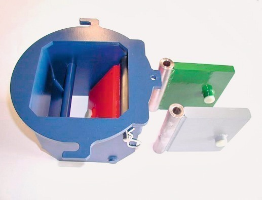
There are different concepts for distributing the air over the grate area. Thanks to their Coanda effect lamellar grate plates which also have fine flow slots for fine clinker, IKN coolers require no special air distribution system [5]. The well-tried conventional design concept is to divide the grate area into small compartments where necessary, and to aerate these compartments individually with fans. This concept is still used today by Claudius Peters in the Eta cooler. A new feature of coolers with a shuttle floor is that the grate area can be divided into lengthwise compartments, with separate aeration devices for the critical edge zones of the grate. Other manufacturers make use of self-regulating flaps in the air supply piping for the grate areas (Fig. 18). These flaps throttle the air stream in areas where the air flow resistance of the clinker bed is lower (e.g. due to coarse clinker). This has the aim of preventing inadequate heating of the air as it flows through the bed of clinker.
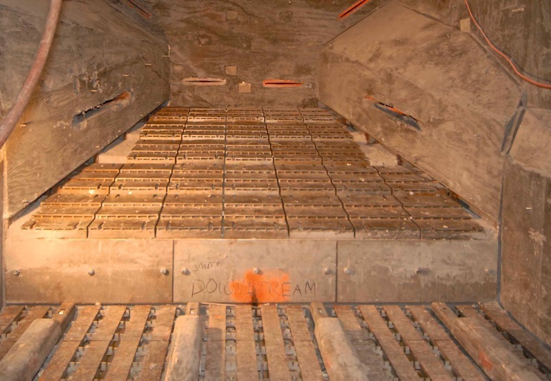
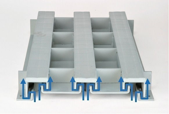
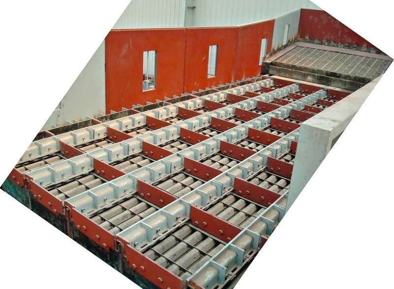
Different designs of grate plate are in use. Aside from the lamellar types, the most widespread are cassette or trough-type plates (Fig. 19), which are practically wear-free. Lamellar plates have a material wear rate of less than 0.015 US$/tcli. [5]. Apart from the static inlet grate with its inclination of about 15°, almost all manufacturers make use of horizontal cooler grates in the section with moving components. Compared to a grate inclination of 5° and a grate length of 20 m, this allows the overall height of the cooler to be 1.7 m lower. However, if a roll crusher is installed between the grates for intermediate crushing of the clinker, the overall height has to be almost 3 m higher. Combi-coolers with several in-line cooler grates are operated with constant clinker conveyance speeds. This keeps the clinker bed height almost constant over the entire length of the cooler. Nowadays, compact hydraulic grate drive units are significantly more reliable and the clinker conveyance efficiency has also increased to around 75 % [11]. The problem of material falling through the grate remained unsolved until the advent of the 4th and 5th generation coolers.
According to a study [12] carried out by OneStone Consulting, a total of 220 new coolers were ordered in 2007 and 2008 (excluding local deliveries in China). Figure 20 shows FLSmidth to be the market leader for new coolers, with a market share of 30 %, closely followed by IKN with 25 %. The TOP 5 cooler vendors, including Polysius, Claudius Peters and KHD, account for 87 % of the market. Chinese plant engineering firms like Sinoma, with the Chinese design institutes (TCDRI, NCDRI and CDI) (Fig. 21), as well as CNBM (design institute HCDRI) and Jiangsu Pengfei etc. have meanwhile achieved a market share of 8 %. Other Chinese specialists, like Jixin Heavy Machinery, have so far only been active on their domestic market. In this connection it must be taken into account that Chinese plant engineering firms have depended on cooler specialists such as IKN and Claudius Peters in numerous international projects. Further cooler manufacturers include specialists like CemProTec, Fons Technology and Satarem.
The number of cooler modernization projects (excluding local deliveries in China) decreased from 48 units in 2007 to 34 units in 2008 [12]. The market leaders for cooler modernization in both years were the cooler specialists IKN, Claudius Peters and CemProTec with market shares of 36 %, 29 % and 13 % respectively (Fig. 22). FLS also achieved a market share of 13 %. Polysius and KHD are included under “other”. This figure clearly shows that cooler specialists are well ahead of the competition in the case of cooler modernization orders. One reason for this may be that turnkey plant engineers like FLS, Polysius and KHD concentrate on complete kiln systems and new plants. On the other hand, the above figures clearly confirm the competence of cooler specialists, who are also frequently contracted to modify existing coolers supplied by turnkey suppliers.
Conversion or modernization of planetary coolers, as described in [13], have become rather rare. Most of the conversion projects involve increases in the capacity of existing coolers and the installation of static inlet grates. Such conversions are often aimed at achieving better cooler efficiency rates, reducing the amount of heat in the cooler vent air and decreasing the specific fan and drive powers [14]. The range of possible conversion measures comprises modification of the grate and improved grate seals, mounting of heat shields to regulate the combustion and cooler vent air volumes, installation of new grate drives and grate bearing assemblies, optimization and replacement of fans and improving the cooler control system, e.g.by installing clinker bed height sensors as part of the stroke frequency control loop. Conversion modules for coolers of the 4th generation have also become a discussion topic recently.
Cooler innovations have rapidly increased in number in recent years. With regard to the grate cooler‘s mechanical equipment, one would think that hardly any scope remained for something really new. The RDC cooler from CemProTec shows this assumption to be false. Further innovations can be expected as a result of the increasing demands placed on WHR systems for energy recovery in cement plants. Possibly this trend will lead to more multi-stage coolers with intermediate crushers, because the results achieved with such systems show that cooler vent air temperatures increase while the cool clinker temperatures remain practically constant. Further aspects are improved duotherm configurations for the cooling air, with recirculation of the cooler vent air to the hot zone of the cooler in order to reduce CO2 emissions and air-cooled crushers installed, for example, subsequent to the static inlet grate of the cooler.
Überschrift Bezahlschranke (EN)
tab ZKG KOMBI EN
This is a trial offer for programming testing only. It does not entitle you to a valid subscription and is intended purely for testing purposes. Please do not follow this process.
This is a trial offer for programming testing only. It does not entitle you to a valid subscription and is intended purely for testing purposes. Please do not follow this process.
tab ZKG KOMBI Study test
This is a trial offer for programming testing only. It does not entitle you to a valid subscription and is intended purely for testing purposes. Please do not follow this process.
This is a trial offer for programming testing only. It does not entitle you to a valid subscription and is intended purely for testing purposes. Please do not follow this process.