Müllerkalk opts for pneumatic conveyance with ceramic rotary valves
The operators of the Müllerkalk and Wotan cement plants have decided in favour of four pneumatic conveying systems by bulk handling equipment manufacturer Kreisel. This article describes the project from its first planning phase through its final implementation.
1 Introduction
Portland cement producer Wotan Zement and lime supplier Müllerkalk are both medium-range, fami-ly-owned enterprises located in Üxheim-Ahütte, in the Volcanic Eifel region. Their products are derived from limestone found in the Hillesheim limestone hollow.
Müllerkalk makes burnt and unburnt lime products and unburnt dolomite products and markets fired items such as powdered white lime, quick lime, lump lime and white lime hydrate. The Wotan Portland cement plant, in turn, makes about nine kinds of cement, all available as bag or bulk goods.
At the company’s new mixing plant...
1 Introduction
Portland cement producer Wotan Zement and lime supplier Müllerkalk are both medium-range, fami-ly-owned enterprises located in Üxheim-Ahütte, in the Volcanic Eifel region. Their products are derived from limestone found in the Hillesheim limestone hollow.
Müllerkalk makes burnt and unburnt lime products and unburnt dolomite products and markets fired items such as powdered white lime, quick lime, lump lime and white lime hydrate. The Wotan Portland cement plant, in turn, makes about nine kinds of cement, all available as bag or bulk goods.
At the company’s new mixing plant (commissioned in 2014), diverse additives are mixed into the certified basic products to obtain sought-after blended products for higher-value use in sewage systems, building materials, agriculture, road building and soil amelioration.
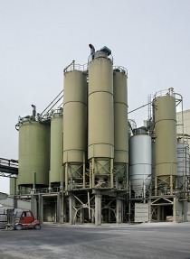
Now that the second phase of construction and expansion has been completed, Müllerkalk is able to tap preproducts from ten different storage silos for their broad array of blended products.
During the main construction season, and for some customer segments, it is a real logistical challenge to keep the silos well stocked and all products available. Consequently, Müllerkalk has implemented two silo feeding options.
Products for delivery are blown directly out of road tankers and into the silos.
2 Planning phase
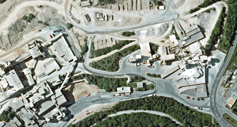
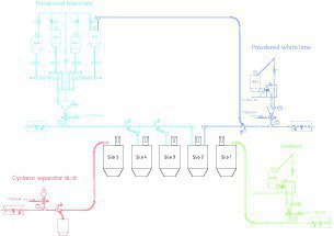
The draft planning stage for Müllerkalk’s new conveying systems began in January 2014. The first goal was to enable pneumatic transfer of various grades of powdered limestone from the existing storage silos to the new mixing plant. It soon became clear, however, that powdered white lime, cyclone separator dust and cement also would have to be transferred by pneumatic means from the neighbouring Wotan cement works over to the new mixing plant. Logistically speaking, the real challenge here was that the starting points of pneumatic conveyance were spread all over the entire Müllerkalk and Wotan premises. Figure 1 provides a bird’s-eye view of the conveyance pipe runs.
Müller therefore huddled with Kreisel to come up with a number of different potential approaches. Prime importance was attached to making the new mixing-plant feed system reliable, energy efficient, affordable and easily integrable, hence facilitating installation of the new pneumatic conveying systems in Üxheim. In addition to fixed parameters such as material properties and the points of dispatch and arrival, there was also a range of actuating variables and components of decisive importance with respect to the economic efficiency of the conveying systems to be considered. One of the project’s main highlights is the extent of energy savings achieved by installing Kreisel-built ceramic rotary valves, as described in more detail below.
2.1 Reliability
Operation of the new mixing plant is wholly dependent on unlimited availability of the conveying equipment. Any loss of pneumatic conveying capacity would badly disrupt the mixing plant’s performance. Obviously, then, the conveying system had to be made unsusceptible to malfunctioning. This stringent requirement was fully satisfied by the use of a hard-wearing ceramic rotary valve as input unit.
2.2. Energy efficiency
Apart from the operators’ own high standards, the regional power utility tasked the company with the problem of limiting or even reducing its energy consumption. Hence, energy efficient material conveyance emerged as one of the most important parameters for Kreisel Engineering.
2.3 Capital cost
Kreisel planned, built, supplied and installed the system unassisted. The resultant absence of interfaces helped optimize the cost. Further cost reductions were achieved by installing some of the conveying lines underground. That saved the cost of installing supplementary pipe bridges. The cement conveying line was planned and installed to run parallel with a closed-belt conveyor. That, too, yielded positive cost effects.
2.4 Integrability
Having evolved over decades, neither plant was able to offer a perfect set of conditions for the integration of additional extensions and whole new systems. Nevertheless and despite limited geographical prerequisites, the operators still expected optimal solution strategies. Cramped conditions prevailing in all parts of the plant called for lots of creativity.
3 Solution strategies
As a rule, fine-grain bulk material like cement, raw meal, fly ash or coal is conveyed pneumatically, if a complicated conveying route is involved. The bulk solid travels through a pipe system with the aid of a hydraulic gas. The friction occurring between the bulk solid and the pipe wall, together with the work-energy expenditure for lifting the material through vertical conveying lines, causes loss of pressure in the hydraulic gas. Consequently, for product-transport purposes, the hydraulic gas must be pressurized to a system-specific level before the bulk solid can be injected into the flow of gas passing through the pipe at system operating pressure. Various types of input system are available for this purpose. In the past, elaborate pressure-vessel systems or screw pumps were used, but then, more than a decade ago, heavy duty ceramic rotary valves (type ZSV-H by Kreisel GmbH & Co.KG) emerged as a preferable alternative.
Three types of input system are described in brief below:
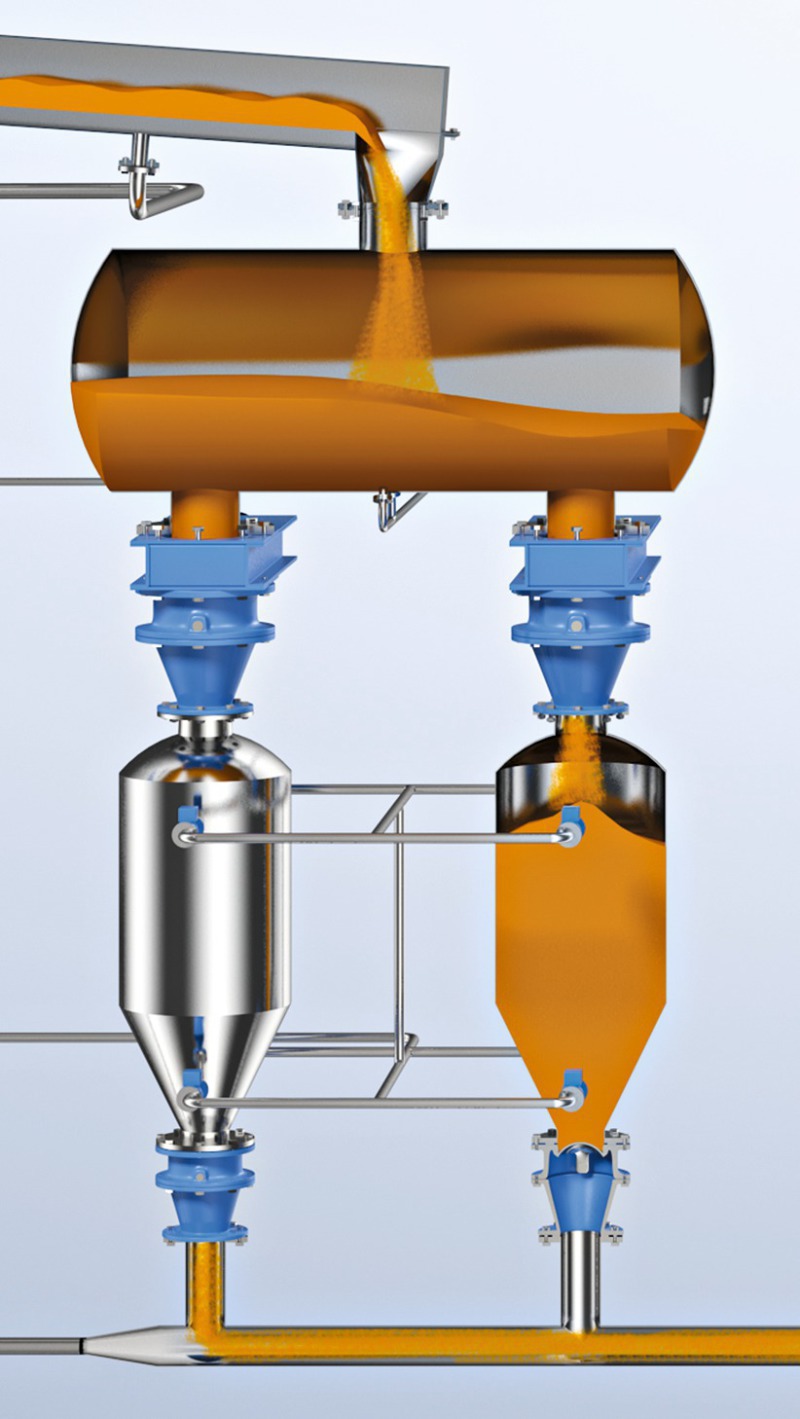
3.1 Pressure vessel
The flow of gas coming out of the compressed-air station is split up into two fractions, one of which passes to the pressure vessel, while the other enters directly into the conveying line (Figure 2). Depending on the needs of the conveyed product, the gas destined for the pressure vessel may again be divided into two fractions, one of which continues on toward the pressure-vessel cone (which facilitates undisturbed outfeed from the vessel), while the remainder passes directly to the vessel’s head. Pressure-vessel conveyance is an intermittent process in which one full cycle consists of four increments: filling – pressurizing – conveying – depressurizing. During three of those four steps, no bulk solid is actually being conveyed through the pipe. Since the period of active conveyance is shorter than the overall cycle time, accordingly more material has to be conveyed during the conveying phase in order to achieve the required nominal throughput rate. Pressure vessels, however, can handle arbitrary conveying pressure levels and are almost universally versatile in terms of their manageable solids spectrum. Due to the pressures involved, though, “periodic inspections” are necessary, and the compressed-air supply system has to be equipped for compressed-air drying and condensate drainage. [2]
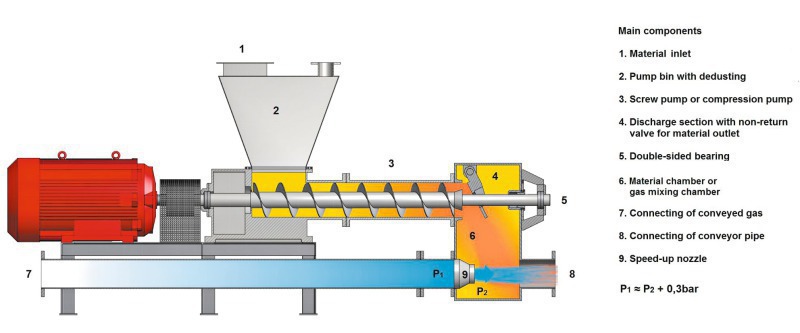
3.2 Screw pump
The next input system considered here is the screw pump (often referred to as a Fuller pump; Figure 3). In this case, the bulk solid drops into the material inlet (1) of the pump’s surge bin (2), which serves to expel the purge gas together with the displaced air from the bulk solid. The latter enters the high-speed compression screw (usually running at about 1000 rpm), which forces it towards the output end, where it is subjected to strong compression. A check flap (4) assists the compression process. This produces a highly compact “plug” that serves solely to seal off the pressure in the conveying pipe. The plug then drops into the outlet section (mixing chamber) of the screw pump, where hydraulic gas transports it into the conveying pipe. In the outlet box, the hydraulic gas has to pass through one or more nozzles (model-dependent). Here, an additional pressure drop amounting to some 0.3 bar occurs in order to accelerate both the conveying gas and the product.
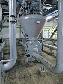
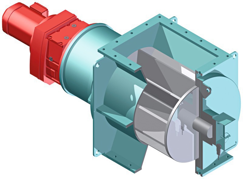
3.3 Rotary valve
Rotary valves (Figure 4) are often used as input units for non-abrasive products. Thanks to a revival of industrial ceramics in this century, rotary valves have come to be “rediscovered”. Kreisel arms its rotary valves with heavy duty industrial ceramics, which are relatively insensitive to impact. The functional principle is simple: The bulk solid drops into the valve’s rotor, which is turning at a (max.) speed of 30 rpm. 180° later, the rotor passes the material into the pressurized conveying line. The requisite air seal between the revolving rotor and the casing is achieved by means of very narrow clearances (<< 0.1mm). No additional pressure losses are caused by nozzles or other internals. The compressed air is supplied by conventional fans or compressors. No compressed-air dryers are needed, because the pressure, as a rule, remains below 2.0 bar (gage).
4 All three systems in comparison
The comparative decision matrix [1] shown here in Table 1 outlines the criteria and their ratings in connection with the individual input systems.
As the matrix demonstrates, ceramic rotary valves best display the required properties. At Müllerkalk, all systems are equipped with rotary valves as input units.
4.1 Reliability
As the comparison shows, ceramic rotary valves rank highest in terms of reliability. Unlike a pressure tank, a rotary valve is an uncomplicated apparatus requiring no complex controls, flaps, valves or signals. Changes in bulk-solid fineness (Blaine), foreign matter and input have no negative impact on the performance of a rotary valve, but would in the case of a screw pump.
4.2 Capital cost
The comparison identifies the pressure vessel as the most costly option, with compressed-air generation emerging as a major cost factor. The cost of the vessel itself depends on the manufacturing requirements for satisfying the pressure equipment directive. Taking cement conveyance as an example, the payback time for the additional cost would be about 18 years. In the case of screw pumps, internal pressure losses often necessitate inclusion of a more expensive compressor. Rotary valves, however, operate more economically, as they only require less expensive fans.
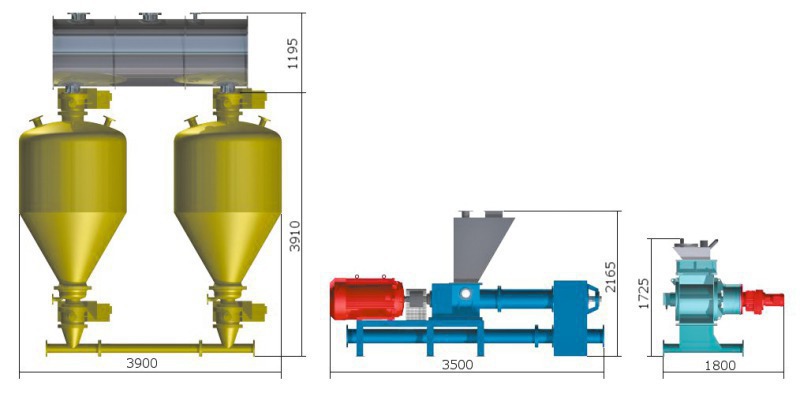
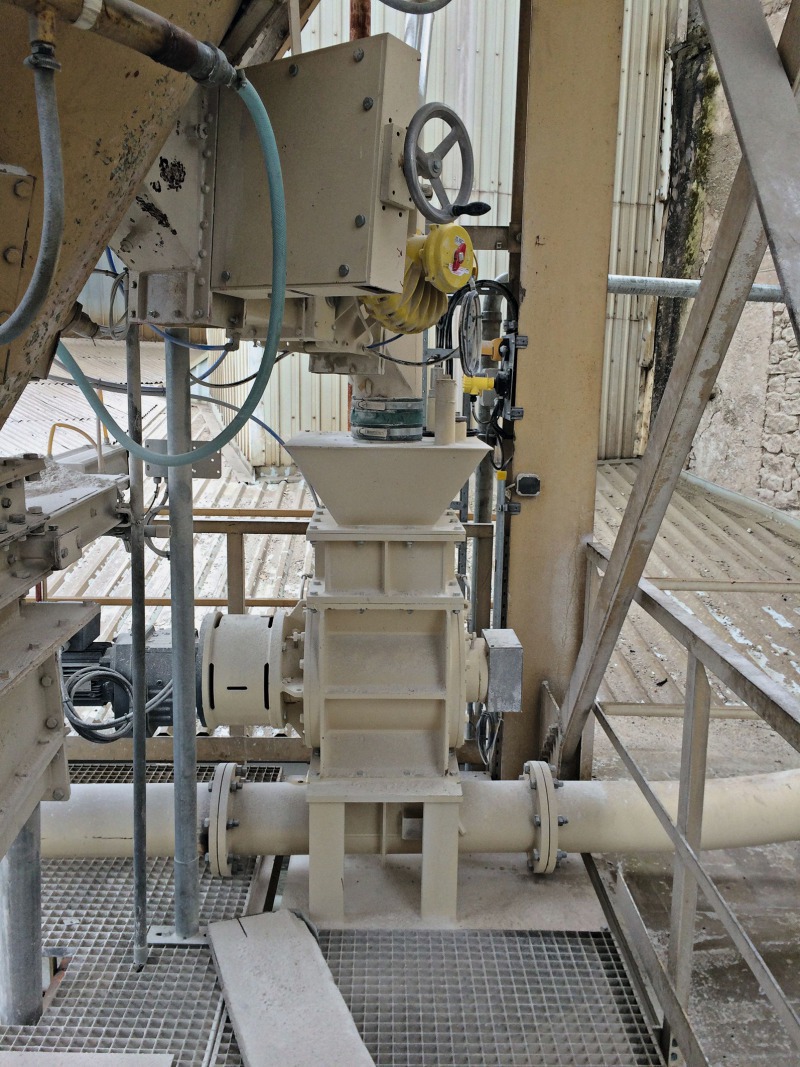
4.3 Integrability
Integrability poses the greatest challenge. All plants considered had to contend with spatial constraints. Figure 5 compares the clear-height requirements of the three input systems for lime powder conveyance. Figure 6 exemplifies the confined local conditions. Indeed, all conveying systems were subject to spatial constraints, so pressure-vessel conveyance was precluded from the very beginning. The small reservoir above the rotary valve is fed by one of four silo discharging screws, depending on the nature of the lime powder being handled. The rotary valve then feeds the lime powder into the conveying pipe. The rotary valve used for handling the lime powder is situated directly above a loaded truck. The butterfly valve linking the rotary valve to the conveying pipe is mounted below the platform. Since every centimetre saved on installed height was important, the clearance between the butterfly valve and the truck was squeezed to less than 10 cm,. All this explains why rotary valve conveyance was preferred.
4.4 Energy efficiency
When it comes to energy efficiency, pressure vessels are undisputed. On the other hand, pressure drops attributable to compressed-air drying and cooling cause unnecessary increases in energy consumption and make it difficult to achieve a clear-cut energy contrast. However, compared with the other two alternatives, this option involves no additional energy losses in the form of gas leaked from the rotary valve, for example, or input power required for the screw pump. Regarding the power input needed for a conventional-type screw pump as compared to that required for a ceramic rotary valve in, say, a cement conveying system, the superior energy efficiency of rotary valves is clear to see. A screw pump requires some 50 kW more input power than a rotary valve with a comparable volumetric delivery capacity. The latter operates on a mere 1 kW or so. That is one of the main factors in favour of replacing screw pumps with ceramic rotary valves by Kreisel. Table 2 contrasts the energy situation of two alternative systems for lime-powder conveyance: the “rotary valve” and the “screw pump”. As the table documents, a rotary valve logging 2000 hours of operation per year can save 102 000 kWh. The Müllerkalk/Wotan project was therefore geared to exploiting that potential.
5 Implementation phase
As mentioned above, the subject conveying systems are situated far apart, so no major synergy effects were able to be achieved in terms of common piping. Table 3 compares the systems’ essential parameters.
The schematic flow diagram (Figure 7) provides an overview of the scope of the processing equipment, also indicating the versatility and flexibility of the process control system. This setup, accomplished by Nikolaus Müller Kalkwerk-Natursteinwerke, is able to flexibly convey the individual product to any desired battery of silos.
The project planning effort had to deal with different sets of requirements for each system.
5.1 Cement conveying system
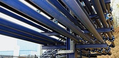
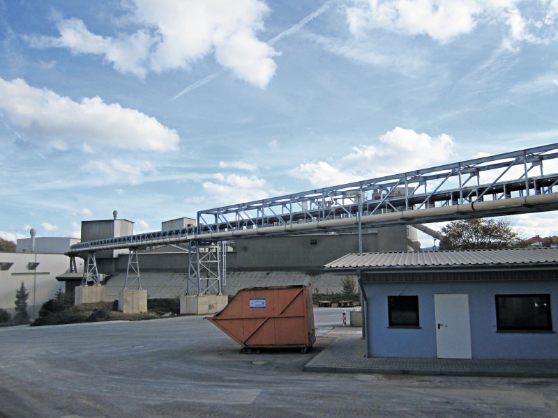
The cement handling process begins at one of Wotan’s loading silos. This silo has a side outlet in its cone. A pre-existing proportioning roller assembly controls the transport capacity. Thirty-six meters downstream, a vertical conveying section extends up 31 m. Next, the conveying pipe runs some 150 m in parallel with a closed-belt conveyor. At the beginning of the project, planning of the closed-belt cement conveyor was already at an advanced stage. Thanks to good coordination by Müllerkalk, both projects were able to be smoothly implemented in parallel. Figure 8 shows the run of the two systems.
5.2 Powdered white lime conveying system
The system configuration is comparable to that of the cement conveying system, except that the planners had to provide for a self-supporting length of some 30 m, because any additional support would have interfered with plant accessibility. That criterion was achieved with a cost-effective supporting structure in which the conveying pipe itself serves as a load-bearing element.
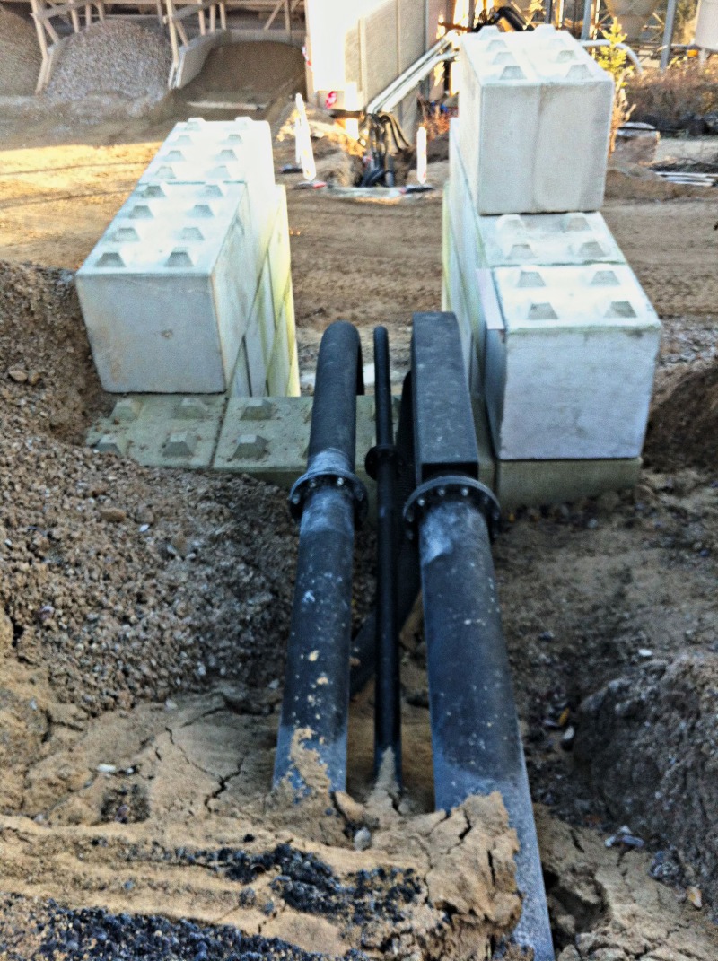
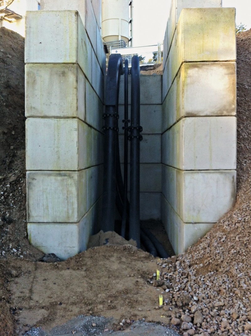
5.3 Underground piping
The piping near the end of the conveyance route leading to the storage silo was installed underground. The last 50 m were designed to tolerate the weight of passing trucks and wheel loaders, i.e., they stretch out under load. Special-purpose paint prevents corrosion of the buried pipes. Figures 9a and 9b show the point of transition where the pipes emerge out of the first underpass leading to the second plane.
5.4 Erection
Kreisel engineered, produced and installed the entire scope of new plant, including all piping and routing. The installation work, depending as it did on plant availability, took about four months in all. The downtime for day-to-day operations was minimized as much as possible. In fact, implementation of the new systems caused no production interruptions whatsoever. Commissioning took place in January and February of 2015. Thanks to very good coordination between Müllerkalk and Kreisel, the new sections of plant were commissioned with no loss of production by exploiting the available production timeframes and were therefore available for use during boom periods.
6 Summary
In 2014/2015, Müllerkalk put up a new mixing plant to extend the company’s product array. This involved installing four new pneumatic conveying systems. In cooperation with Kreisel, the so-called input units were analyzed with respect to four essential criteria: energy efficiency, capital cost, integrability and reliability. The results showed that ceramic rotary valves best fulfilled the given set of requirements. Now, after their first year in operation, the Kreisel-planned, -constructed and –installed systems are working smoothly and to the complete satisfaction of Müllerkalk.
//www.kreisel.eu" target="_blank" >www.kreisel.eu:www.kreisel.eu
Überschrift Bezahlschranke (EN)
tab ZKG KOMBI EN
This is a trial offer for programming testing only. It does not entitle you to a valid subscription and is intended purely for testing purposes. Please do not follow this process.
This is a trial offer for programming testing only. It does not entitle you to a valid subscription and is intended purely for testing purposes. Please do not follow this process.
tab ZKG KOMBI Study test
This is a trial offer for programming testing only. It does not entitle you to a valid subscription and is intended purely for testing purposes. Please do not follow this process.
This is a trial offer for programming testing only. It does not entitle you to a valid subscription and is intended purely for testing purposes. Please do not follow this process.