Long-distance conveyance using a pneumatic system
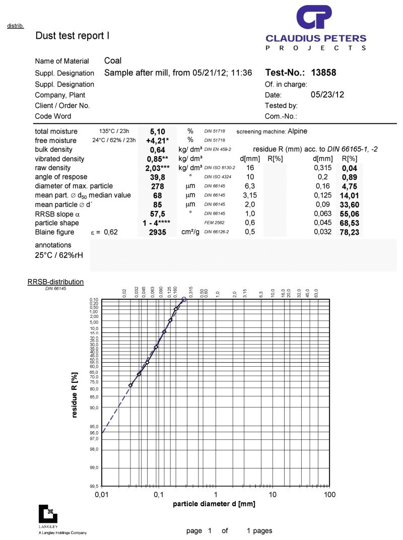
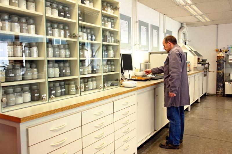
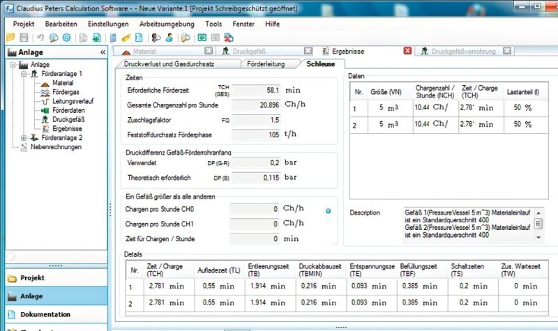
The basis for designing a pneumatic conveying system is precise knowledge of the material to be conveyed. This is gained by means of raw material analyses that determine, for instance, the granulometric distribution, bulk density, moisture content and surface properties. On the basis of the specified system parameters and the determined material data, the process technological designing of the system is carried out, generally using special computing programs.
1 Introduction
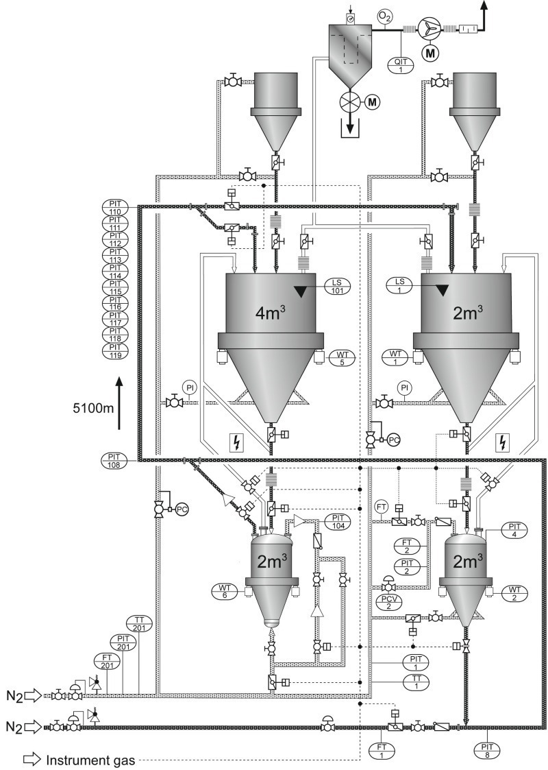
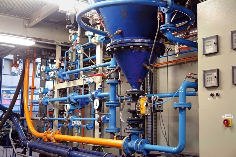
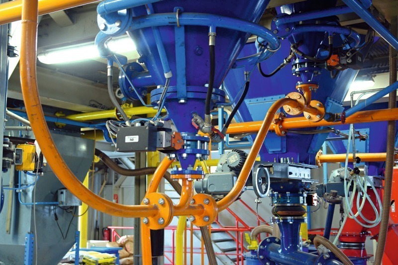
Subsequent to the general designing of the conveying system and its components, such as pressure vessel volume, type and inside diameter of the piping, the expected pressure drops and the conveying gas requirement, planning of the measurement and control equipment took place under consideration of all safety-rel-evant aspects (Figs. 3 and 4). As this project involved the conveyance of coal dust, the entire conveying system including the dedusting equipment was rendered inert by means of external nitrogen evaporators. The monitoring takes place online.
2 Design of the conveying system
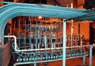
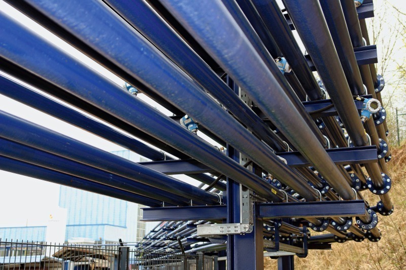
The feeding hoppers are dedusted via a filter unit. The O2 monitoring is performed online in the dedusting pipe. Due to their complexity, the demands placed on the measurement and control technology are compa-rable with those of an industrial scale conveying system. In fact, the measurement and control system of the test plant had to be even more flexible and comprehensive. Over the entire length of the test line, one very particular focus of the test work was analysis of the behaviour of the material being conveyed. To achieve this, 15 pressure transmitters (Fig. 8) were installed in the conveying pipe in order to continuously record the pressure gradient over the entire test line of 5.1 km.
When designing a pneumatic conveying system, not only the reliable transportation of the material must be assured, but also the aspect of possible wear inside the conveying pipe and the pipe bends has to be taken into consideration. During the conveyance the conveying gas expands due to the decreasing back pressure in the conveying pipe, which results in higher conveying velocities. And one of the effects of higher velocities is higher wear. As a consequence, it is necessary to increase the inside diameter of the conveying pipe at previously calculated points as the distance from the infeeding point increases. At the same time, it has to be assured that the velocity does not fall below the minimum required for reliably transporting the material. Determination of these inside diameter increase points requires complex computation operations, and a certain amount of expert experience is also necessary.
To ensure that the material is dosed into the conveying pipe at a constant and monitored rate, the two pressure vessels are mounted on load cells. The feed rate can be regulated by means of flow-regulating valves at the outlets of the pressure vessels as well as by variation of the top pressures in the pressure vessels. To guarantee the minimum velocity at the point of material infeeding into the conveying pipe, the conveying gas velocity is determined before feeding and kept constant throughout the starting-up, operation and running-down processes. This procedure ensures that material transportation is carried out independently of the material feed rate – i.e. also independently of the variable back pressure from the conveying process.
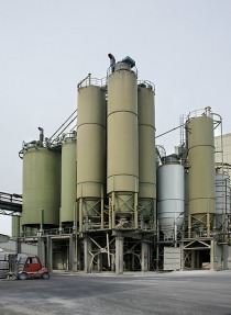
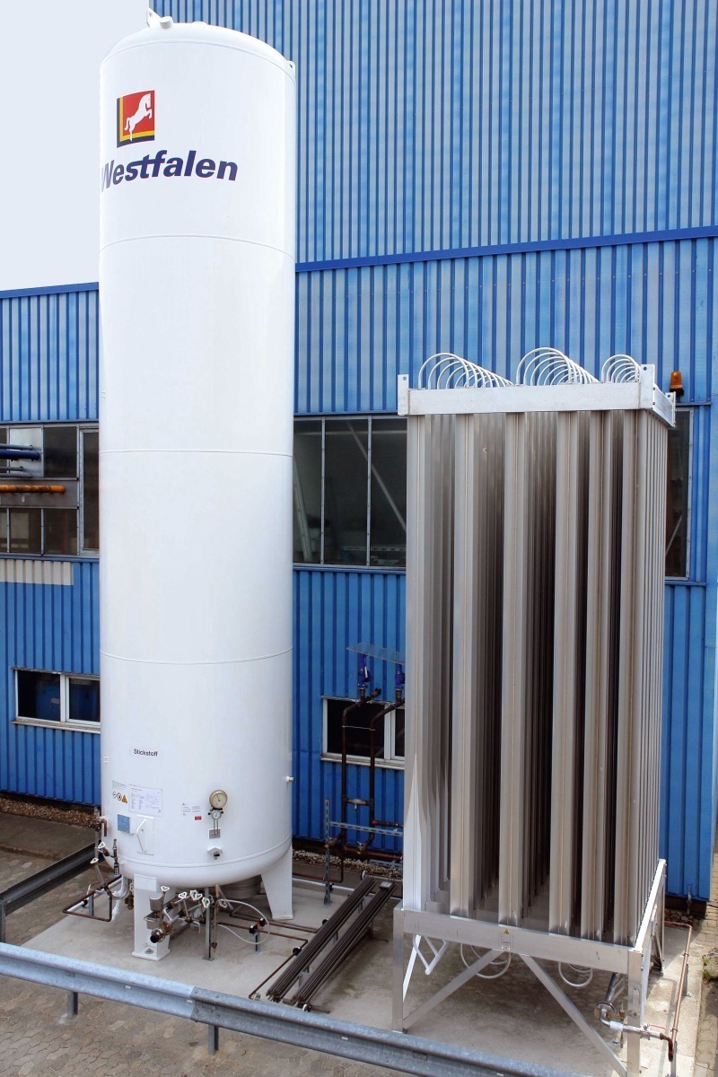
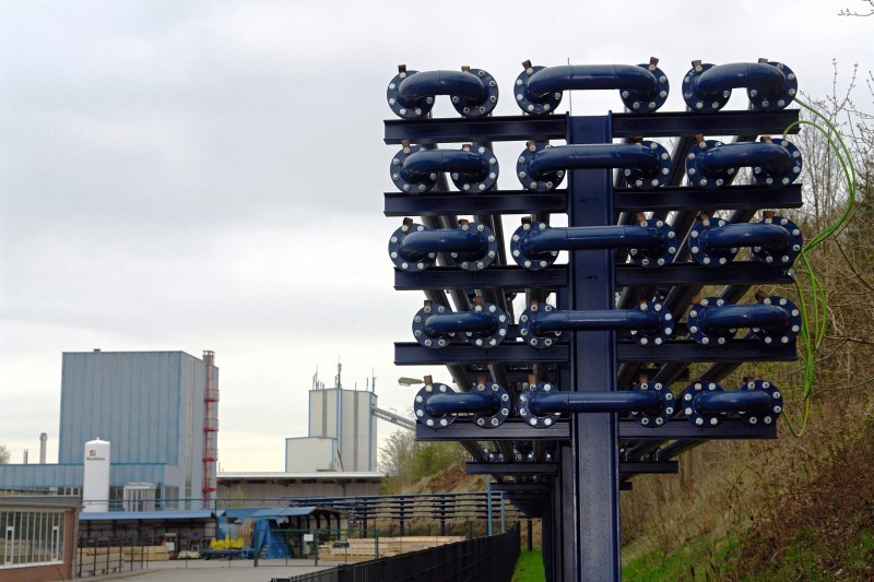
Dictated by the industrial safety requirements, it is only possible to operate the system with nitrogen. Because of the not inconsiderable consumption of conveying gas, external nitrogen accumulators had to be linked to suitable vaporizers and connected to the test system. In the meantime, a significantly larger nitrogen accumulator has been retrofitted (Fig. 9) in order to ensure independent operation of the conveying system over operating periods of several hours.
3 Tests
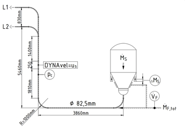
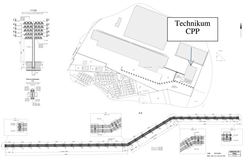
The overall course of the conveying pipe is depicted in the installation drawing shown in Fig. 11.
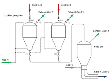
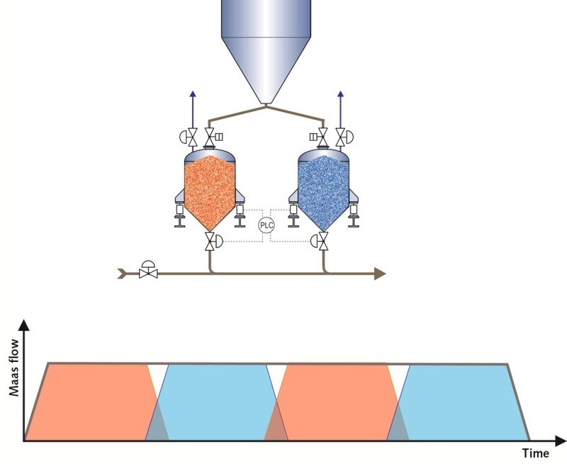
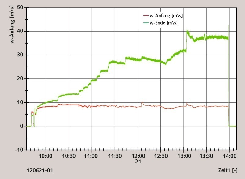
Fig. 12 shows the typical system for long-distance conveying. Two pressure vessels connected in parallel inject the material into a main conveying pipe, which leads into a receiving silo. Uniform material dosing into the conveying pipe is decisively important for reliable transportation. This is achieved by regulating the pressure vessel discharge flow by means of dosing valves. While one valve is slowly closing, the other is correspondingly opened. With optimal regulation, the conveyed mass flow remains constant. Conveyance can be effected by means of two or several pressure vessels connected in parallel. The main conveying pipe is generally filled with pressurized air. The top pressure in the pressure vessel controls the discharge velocity. The preset and controlled top pressure in the pressure vessel equals the maximum back pressure to be expected in the main conveying pipe plus approx. 0.3 bar. When the shut-off valve is opened the conveyance begins. The conveying gas flow volume is recorded in opm3/h and regulated via a control valve that governs the initial velocity required for conveyance of the particular material. At every operating point it is thus ensured that no plugs of material can form in the conveying pipe. Fig. 13 depicts the velocities from the material infeed point to the receiving silo.
In this example an initial conveying velocity of approx. 9 m/s was selected (red line). The green curve represents the course of the velocity over the conveying route with increasing throughput rates. A higher back pressure at the start of the conveying pipe – caused by increasing the material feed rate – leads to a higher ultimate velocity at the end of the conveying pipe. The ultimate velocity is always a function of the conveying gas flow volume and also of the conveying pipe inside diameter. A larger conveying pipe diameter would result in a reduction in conveying velocity. However, a critical aspect of progressively increasing the pipe inside diameter is that the reduction in conveying gas velocity at the transition points from smaller to larger pipe inside diameters often cause material to drop out of the flow. For this reason, an adequate reserve has to be designed into the difference between the actually used conveying gas velocity and the minimum velocity.
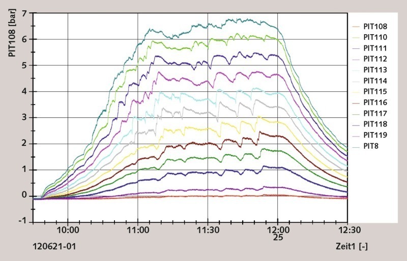
In particular, starting-up processes with a small amount of material and therefore a low back pressure lead to low conveying velocities at the inside diameter transition points. If the material loading in the conveying gas is increased, higher ultimate velocities can be expected. Special attention has to be paid to this problem when designing a long-distance conveying system with several pipe inside diameter transitions. In order to monitor the material‘s conveying characteristics over the length of the test system, pressure transmitters were installed at intervals of approx. 500 m. Fig. 14 depicts the pressure gradient over the length of the conveying route during the testing.
The material feeding was slowly increased to a throughput of approx. 1.1 tph. The pressure drop between the infeeding point and the receiving silo is clearly shown in Fig. 14, as is the pressure increase during the start-up phase. After approximately one hour the stable conveying phase is reached. The variations in the pressure curves are caused by the pressure vessel change-over. During the stable conveying phase the curves run approximately parallel. Pressure fluctuations travel through the conveying pipe with a slight time offset. The average material velocity in the conveying pipe is approx. 1.4 m/s, which indicates that dune conveying is taking place.
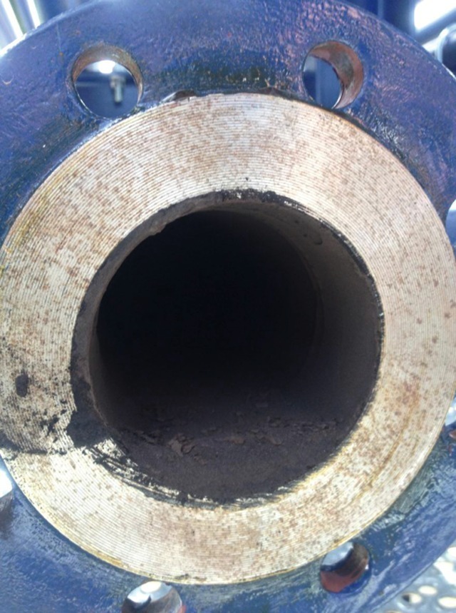
This naturally provokes the question as to whether such a system could be restarted to proper operation after an emergency shutdown or a power failure has taken place. However, in the presence of the client a restart was successfully tested as part of the system trials. Furthermore, after a stoppage the conveying pipe was taken apart at several places and the depth of the material bed was measured. As shown in Fig. 15, there was only a thin layer of material at the bottom of the pipe.
The conveying system can be restarted without any problem as long as the gas flow volume is slowly raised to the level it was at before the shut-down. Correspondingly, material conveyance begins at the end of the conveying pipe. As the conveying gas flow volume increases, the zone where the deposited material starts to be conveyed moves progressively towards the infeeding point.
A further important aspect during restarting the coal dust conveying system is ensuring the inert operation. Thanks to the low amount of conveying gas fed into the system, the pipe and the cleaning system are first flushed before any material is conveyed. This makes it impossible for explosive mixtures to form. The O2 measurement in the exhaust gas system does not send a release signal for renewed material infeeding until the O2 value is safely below the limit.
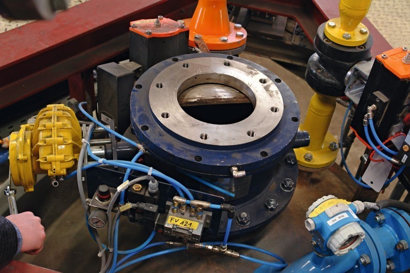
The design of the test system provided for possible shortening of the conveying route by simple reconnection at pipe bends (Fig. 16).
4 Conclusions
very low wear
low emissions: no dust nuisance and hardly any noise
high degree of fire and explosion safety
high level of automation
hardly any maintenance requirement
flexible conveying pipe configuration
change-over by means of two-way valves in the conveying piping allow different receiving silos to be fed without interrupting the conveyance
complete emptying
low space requirement
high availability
Überschrift Bezahlschranke (EN)
tab ZKG KOMBI EN
This is a trial offer for programming testing only. It does not entitle you to a valid subscription and is intended purely for testing purposes. Please do not follow this process.
This is a trial offer for programming testing only. It does not entitle you to a valid subscription and is intended purely for testing purposes. Please do not follow this process.
tab ZKG KOMBI Study test
This is a trial offer for programming testing only. It does not entitle you to a valid subscription and is intended purely for testing purposes. Please do not follow this process.
This is a trial offer for programming testing only. It does not entitle you to a valid subscription and is intended purely for testing purposes. Please do not follow this process.