KHD combustion chamber – flexible use of alternative fuels in the cement plant
Modern combustion technology permits extremely flexible reaction to the varying properties of alternative fuels.
1 Calciner system
One important criterion for the calciner design is the gas retention time. Theoretical calculations [1] and practical experience regarding the course of hot meal calcination show that at the stated temperature window and normal fineness of the preheated hot meal, the target calcination rate of 90 to 95 % is achieved in less than 3 s.
The combustion process in the calciner thus takes place under extremely difficult conditions. The low partial pressure of oxygen and the low overall combustion temperature, caused by the high energy demand of the calcination reaction, result in a kinetic inhibition of the combustion reaction. To counteract this, the calciner should be so designed that the retention time is longer than 3 s. Designing for the required retention time is thus decoupled from the requirements of the calcination process, so that it is now only dependent on the quality of the calciner fuel.
Nowadays, the usual gas retention times of the calciner are 3–4 s for lignite, hard coal, natural gas and oil and over 5 s for fuels that are difficult to ignite, such as anthracite or petroleum coke. The technological characteristics of fuel – taking solid fuels as an example – that influence good burnout under the combustion conditions in the calciner are then essentially restricted to its reactivity (ignition and char burnout) and its particle size. The reactivity can only be influenced by the drying and size-reduction of the fuel, and is essentially dependent on the content of volatile components. The higher the content of volatiles, the better and faster the ignition of the fuel. The particle size depends on the extent to which the fuel can be cost-effectively ground. The finer the particle size distribution and the lower the amount of oversize material, the shorter the time required for complete burnout.
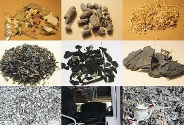
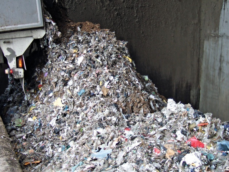
In contrast to the above-mentioned primary fuels, the number of possible secondary, alternative fuels is far larger, which significantly increases the range of difference in their combustion properties. In most cases, alternative fuels have higher moisture contents, consist of larger particles and have a lower energy content and calorific value. The moisture content causes delayed ignition of the fuel and the larger particle size results in a longer burnout time. The calciner geometry therefore has to be so designed that gas retention times of > 5.5 s can be achieved, in order to obtain the operational flexibility needed for the burning of fuel with constantly altering properties.
Under the described firing conditions, the quality and quantity limits of the alternative fuels used in the calciner are quickly reached. Quality means higher calorific value, low moisture content, low particle size and therefore a higher degree of processing with the corresponding expense involvement, as well as minimal chlorine and sulfur contents. Quantity refers to the maximum usable amount of alternative fuel with which the overall process operation can be kept stable.
2 Requirements placed on the calciner
3 PYROCLON R with combustion chamber
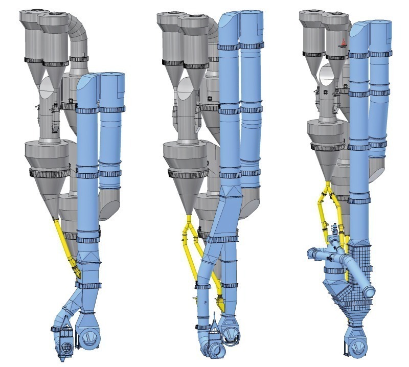
To enable the complete combustion of alternative fuels of lower quality and in greater quantity in the calciner, the PYROCLON R calciner can be equipped with a combustion chamber. This is designed for the combustion of 100 % of the calciner fuel. For this reason, no other combustion points are needed and there is no fuel conveyance equipment at the calciner. The combustion chamber, which provides substantially improved firing efficiency, is designed, so that it can be retrofitted during the modernization of an existing system.
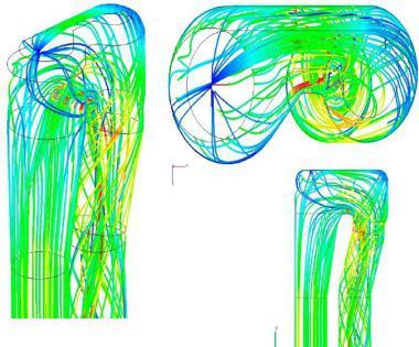
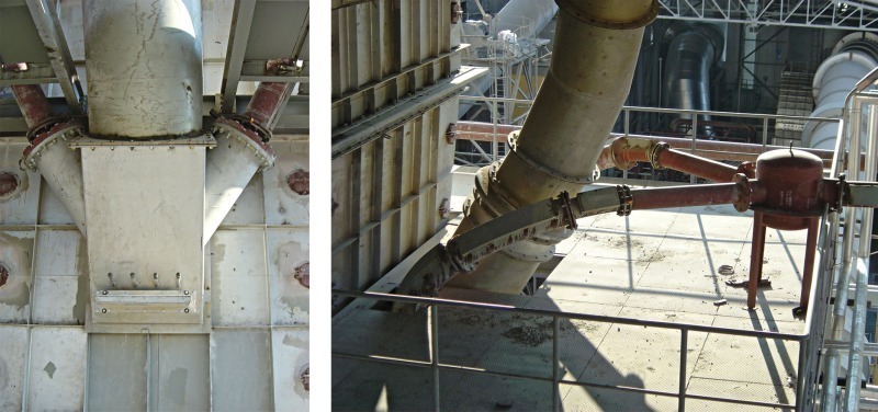
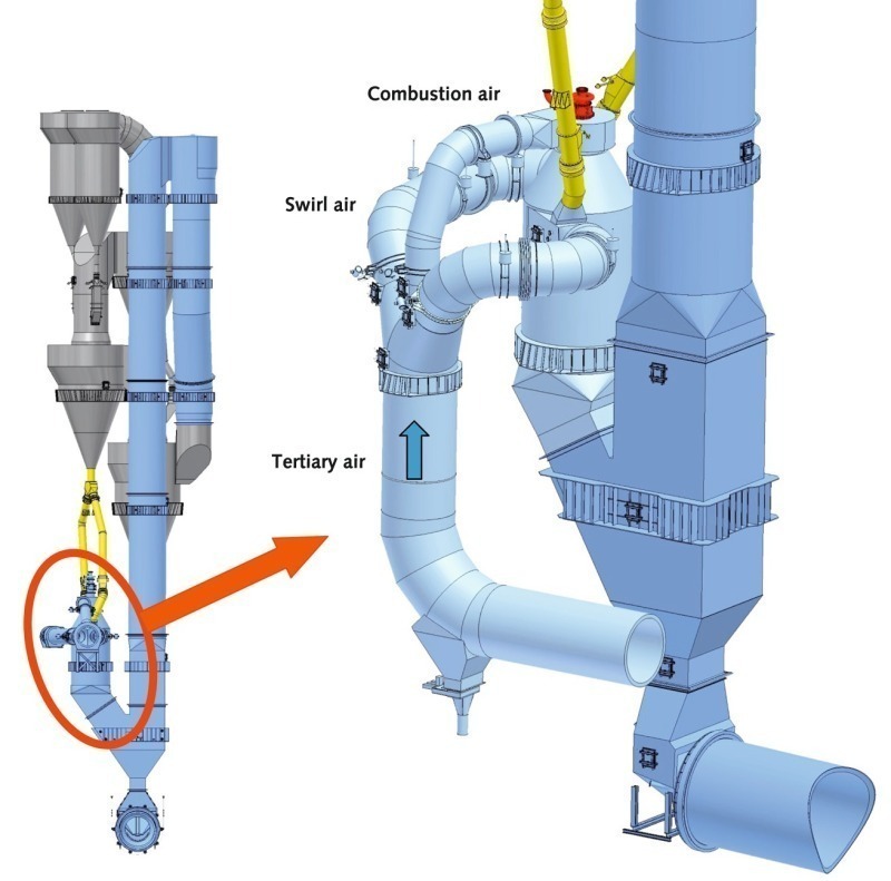
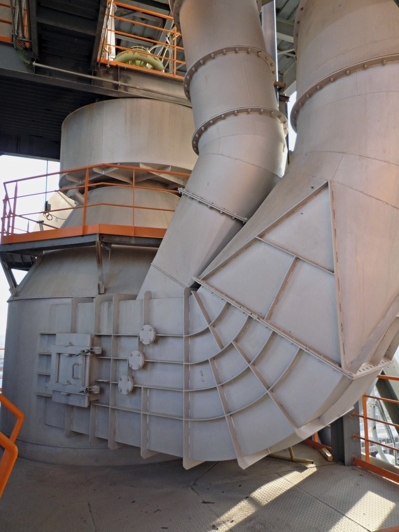
The combustion chamber is mounted vertically at the side of the riser duct of the calciner. The tertiary air is supplied directly to the combustion chamber in three partial streams. One of these partial streams is called the top air (pre-combustion air) and is fed into the topmost point of the combustion chamber in the direct vicinity of the combustion chamber burner. The top air is regulated by a control device and is actively used for controlling the temperature. The two other partial streams are called swirl air and are fed tangentially into the upper, cylindrical section of the combustion chamber. The preheated hot meal supplied from the second-last cyclone is split and fed into the two tangential air ducts and, thus, enters the combustion chamber suspended in the tertiary air stream. A clearer understanding of the combustion chamber arrangement, including the tertiary air connections is provided by Figure 4.
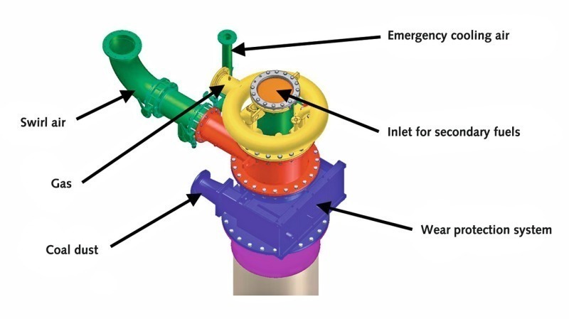
The fuel is supplied via a special burner system. Unlike conventional calciner burners, the combustion chamber burner, similar to the rotary kiln burner, is a multichannel burner supplied with additional swirl air for shaping and stabilizing the flame (Figs. 5 and 6). The burner is designed for the combustion of both primary and alternative fuels. To enable the firing of lumpy alternative fuels, the combustion chamber burner can be equipped with a central pipe of up to 800 mm in diameter. Furthermore, the burner is provided with an ignition burner, which enables direct starting of the combustion chamber without the need for hot tertiary air.
The clear advantage compared to the combustion process in a conventional calciner is that the fuel combustion conditions are similar to those in a rotary kiln: high oxygen concentration, practically no presence of meal in the flame zone, and correspondingly high temperatures.
The high oxygen concentration results from the use of pure, hot tertiary air in the combustion chamber. The burning mixture does not mix with the gases from the rotary kiln until it reaches the end of the combustion chamber. The high temperatures of over 1200 °C at the center of the combustion chamber are achieved by feeding the hot meal into the tangentially connected tertiary air ducts. The meal is thereby guided into a radial entry line and, due to the swirl, mainly becomes concentrated near to the combustion chamber wall. At the center of the combustion chamber, the meal concentration remains low. The chamber is thus divided into two zones, the area of the flame and the area close to the combustion chamber wall. The hot flame, located in the center of the combustion chamber, is able to expend most of its energy on heating up the gas and the fuel particles, which accelerates the combustion reaction. The concentrated fog of meal at the combustion chamber wall protects the refractory lining against thermal overload. Radiation and convection heat from the flame zone is utilized for the meal calcination reaction, preventing the occurrence of undesirably high temperatures near to the wall.
Good ignition of the supplied fuel is assured by the conical design of the combustion chamber roof and by the design of the combustion chamber burner. The conical roof acts as an ignition arch, reflecting the radiation heat in a focused manner directly back into the root of the flame and not, as is the case with a flat roof, reflecting the heat parallel and past the flame. A further advantage of the conical roof design is the self-supporting, and therefore more stable, refractory lining. The combustion chamber burner is provided with a swirl air system. The flame is stabilized by the swirl of the entering primary air. The swirl results in a backflow of already burning fuel and hot combustion gases, which results in early ignition of the fresh fuel entering the combustion chamber.
The combustion chamber temperature is mainly controlled by adjusting the flap position in the top air duct. The top air duct supplies a portion of the hot tertiary air directly to the burner tip and, thus, provides the flame root zone with oxygen. In the case of fuels that are difficult to ignite, such as lumpy anthracite or moist RDF, the top air duct flap is opened. This supplies the flame with more oxygen, increasing the temperatures in the upper section of the combustion chamber and improving the ignition and burnout characteristics of the fuel. Another parameter used for adjusting the firing conditions is the swirl air quantity fed to the burner. An increase in the swirl air quantity results in a more stable, hotter flame. The actual controlling of the overall calciner is then undertaken in classical manner, by regulating the fuel mass flow to the combustion chamber as a function of the calciner outlet temperature and, thus, as a function of the required degree of meal precalcination.
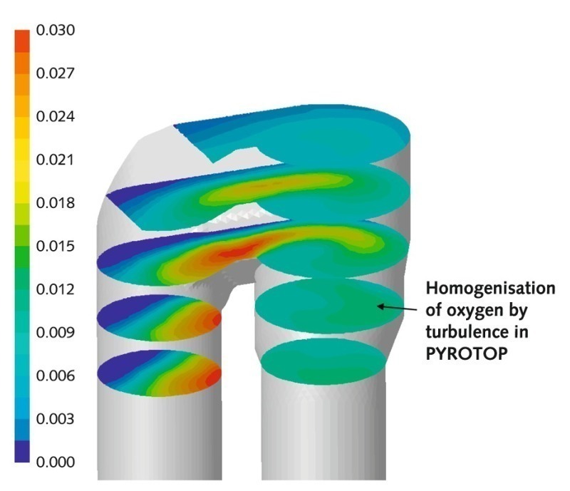
At the point where the combustion chamber is connected to the riser duct of the calciner, above the orifice, there is an intensive mixing of the burning gases with the residual oxygen and the meal. The post-combustion subsequently takes place in the calcination section. Including the combustion chamber, an overall gas retention time of more than 6–7 s is achieved.
The orifice itself is designed to produce higher gas velocities in order to compensate for the additional pressure loss over the combustion chamber and establish a balance between the secondary and the tertiary air. The higher velocity has the advantages that, firstly, the material streams emerging from the combustion chamber are subjected to a good mixing impetus and, secondly, that sufficient momentum is imparted to unburnt lumpy fuel fragments to prevent them dropping directly into the kiln inlet chamber.
One primary measure for reducing NOx emissions is equipping the combustion chamber with a top air duct. This enables a portion of the hot tertiary air to be diverted directly into the upper section of the vertical section of the calciner, before the combustion chamber inlet. Combustion in the combustion chamber and lower calciner section takes place under oxygen-reduced conditions, in a substoichiometric to near-stoichiometric range, thereby impeding the generation of new NOx. The incompletely burnt gases passing through the inlet zone of the vertical calciner section further reduce NOx. Another primary measure for NOx avoidance is the targeted setting of the combustion chamber temperature using the top air pipe to the combustion chamber burner mouth. Here, the temperature can be adjusted in such a way as to prevent the generation of further thermal NOx (which is mainly formed at temperatures above 1300 °C).If the primary measures for reducing NOx emissions are not adequate due to the fuel properties or because of stringent limit value requirements, the calciner can be equipped with an SNCR system.
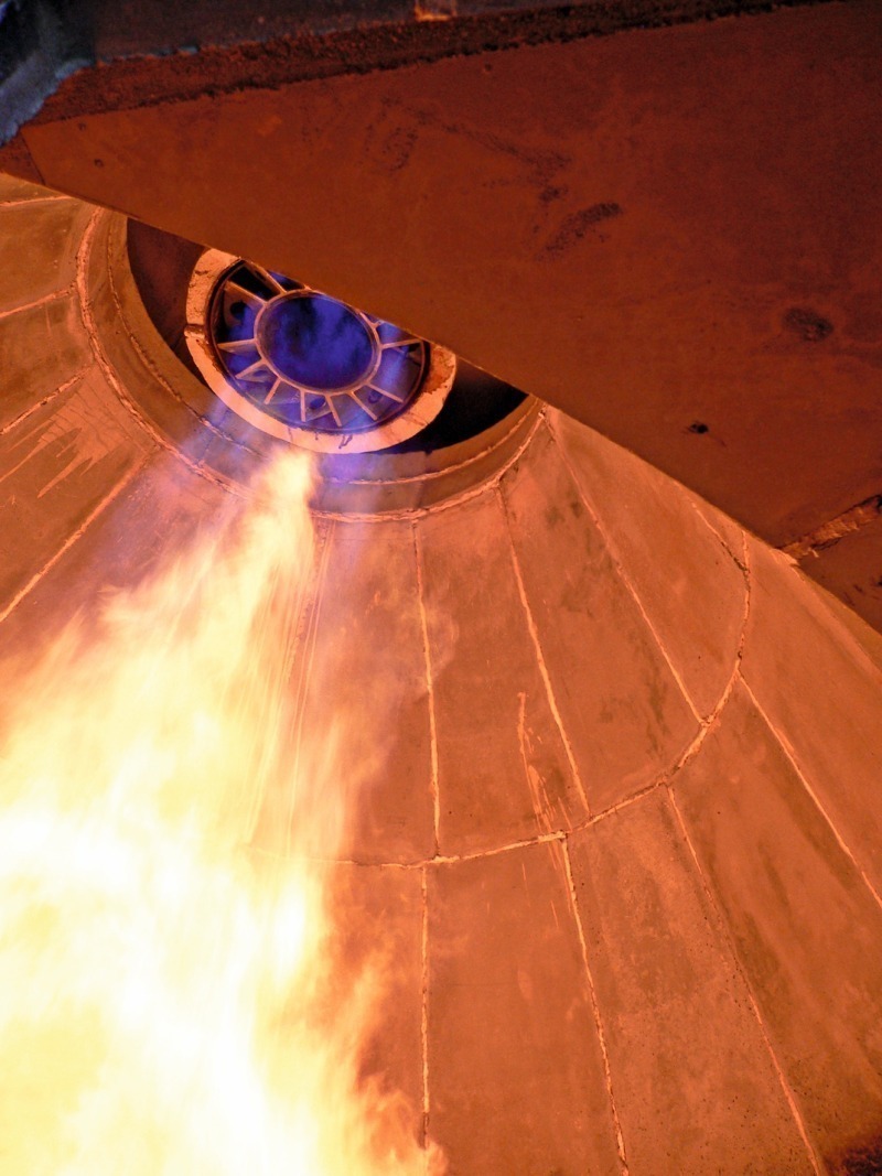
The oxygen-rich and hot combustion atmosphere enable the safe conversion of alternative fuels of lower quality and – most important – of larger particle size in the combustion chamber. One of the advantages of a combustion chamber (Fig. 7) is that the degree of preparation (particle size) of the alternative fuels can be considerably lower, which has a positive effect on the plant’s alternative fuels costs. Another advantage is that the combustion chamber is designed for a significantly broader range of fuels, i.e. it is considerably more flexible. This gives the plant operator far greater room to maneuver in reacting to the strong fluctuations on the market for alternative fuels. As the combustion chamber is designed for the use of 100 % of the calciner fuel, only one handling system is needed for conveying the alternative fuels to the calciner. The combustion chamber has become firmly established in the cement industry, and is recognized as the best available technology for utilizing large quantities of alternative fuels. KHD’s reference list now consists of more than 10 combustion chambers sold.
4 Operating results
The utilization of “solid hazardous waste” is a remarkable feature. Due to the high temperature in the combustion chamber, it is even possible to use alternative fuels that would otherwise have to be expensively disposed of in a special incineration plant.
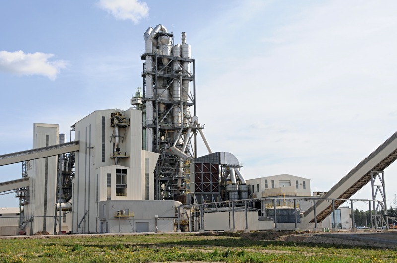
Another PYROCLON R calciner with combustion chamber went into service in April 2009 in the newly constructed CEMEX Broceni cement plant in Latvia (Table 2). The clinker production capacity is 4000 tcli./d, approx. 500 tcli./d more than warranted. In this plant, too, the main feed point for the alternative fuels is the combustion chamber, which has a thermal substitution rate (TSR) of 97 %, corresponding to an absolute fuel mass flow of about 20 t/h. The remaining 3 % is covered by hard coal dust. The background to this is the desire to constantly run the calciner’s coal dosing equipment at minimum capacity in order to be able to react immediately if a problem occurs with the alternative fuels (e.g. blockage or failure of the conveying system). The thermal substitution rate of the entire plant is approx. 70 %. Table 2 shows the different alternative fuels used in the combustion chamber.
5 Conclusions
Acknowledgment
Überschrift Bezahlschranke (EN)
tab ZKG KOMBI EN
This is a trial offer for programming testing only. It does not entitle you to a valid subscription and is intended purely for testing purposes. Please do not follow this process.
This is a trial offer for programming testing only. It does not entitle you to a valid subscription and is intended purely for testing purposes. Please do not follow this process.
tab ZKG KOMBI Study test
This is a trial offer for programming testing only. It does not entitle you to a valid subscription and is intended purely for testing purposes. Please do not follow this process.
This is a trial offer for programming testing only. It does not entitle you to a valid subscription and is intended purely for testing purposes. Please do not follow this process.