Alternative fuels in the cement manufacturing process
Due to the numerous possible sources of alternative fuels, the degree of variability in energy content, ash, moisture, particle size, form, density etc., extensive experience and know-how are necessary in order to identify the effect of co-processing on the clinker production process and, thus, offer the best solutions for the entire application of alternative fuels in the pyroprocess, comprising of the handling and firing systems.
1 Effects on the clinker manufacturing process
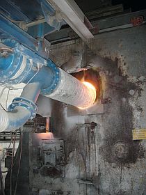
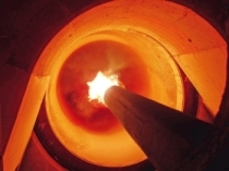
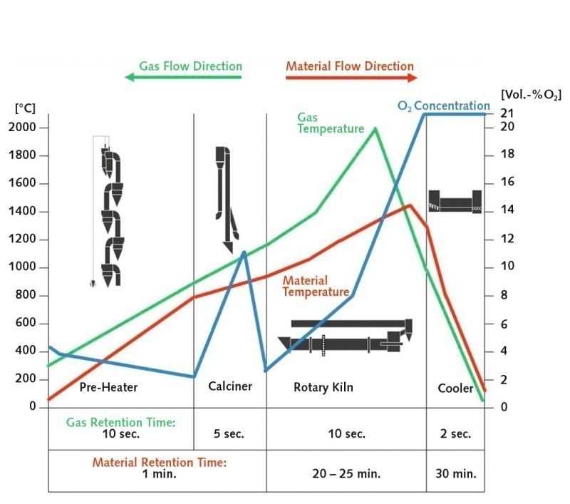
The clinker manufacturing process offers ideal prerequisites for the safe combustion of alternative fuels. Due to the fact that the process involves high temperatures, long retention times, and high oxygen concentrations (Fig. 1) complete conversion of the organic substances is assured. Lime, the main raw material component, produces a basic dust atmosphere which assures safe transformation of the acid elements introduced with the alternative fuels, such as chlorine, sulphur and fluorine, from the gas phase into the solid phase. The mineral...
1 Effects on the clinker manufacturing process
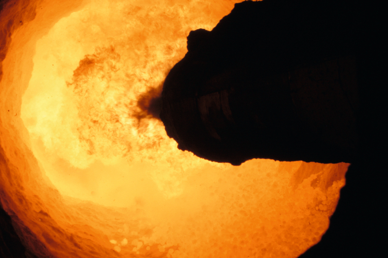
The clinker manufacturing process offers ideal prerequisites for the safe combustion of alternative fuels. Due to the fact that the process involves high temperatures, long retention times, and high oxygen concentrations (Fig. 1) complete conversion of the organic substances is assured. Lime, the main raw material component, produces a basic dust atmosphere which assures safe transformation of the acid elements introduced with the alternative fuels, such as chlorine, sulphur and fluorine, from the gas phase into the solid phase. The mineral components of the alternative fuels replace a portion of the raw material, and are stably bonded into the crystalline structure of the clinker. As a result, no by-products that are dangerous for the environment can be produced.
Beside the environmental and economic advantages offered by the usage of alternative fuels, there are, however, effects on the technological process that have to be known and taken into consideration when executing the project. Significant effects are the higher specific energy requirement, the resulting increased exhaust gas volume, and the corresponding limitation on the clinker production rate. The intake of chlorine and sulphur often increases due to the alternative fuels, and above a certain amount of these elements a kiln bypass system becomes necessary. There are also effects on the clinker chemistry and quality if, for instance, the clinkering zone burner is not suitable for the use of alternative fuels and allows unburnt fuel to react directly with the clinker. Another effect is the influence on dust and gaseous emissions that requires suitable reduction measures to be installed.
2 Firing of alternative fuels in a rotary kiln (SRF)
The firing process in the rotary kiln is very demanding, as the fuel energy ideally has to be provided within the boundaries of the clinkering zone, and a displacement of the heat provision, i.e. a later burning-out of the fuels in the zone extending towards the kiln inlet compartment, has to be prevented. For reasons of clinker quality, it has to be ensured that complete combustion (“burnout”) of the solid structure of the fuels is completed while the fuel is suspended in the gas stream. These prerequisites impose physical (particle size) and chemical (energy content) limits on the usage of alternative fuels, which can, however, be extended by the application of modern burners. The proven PYROJET® burner from KHD Humboldt Wedag is a design advancement that specifically meets the requirements for firing high Thermal Substitution Rates (TSR) of such pre-processed solid alternative fuels.
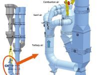
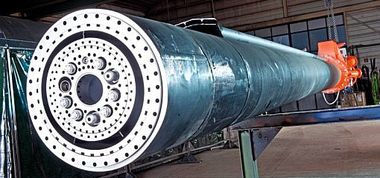
For the firing of Solid Recovered Fuels (SRF) as well as fossil fuels, it is important for the firing system to enable forming of the flame shape with the aid of the primary air system, in order to reliably obtain a stable flame, a massive release of heat in the clinkering zone and complete fuel combustion inside the kiln. To fully satisfy these requirements, the PYROJET® burner (Fig. 2) has two primary air systems, consisting of swirl air and jet air (axial air). The swirl air at the centre of the burner has a pressure of 150 mbar and ensures that the flame is stabilized at the burner tip and that hot combustion gas is fed back to assure quick ignition of the fresh fuel. The jet air has a pressure of up to 900 mbar and ensures that intensive mixing takes place between the flame and the oxygen in the secondary air from the clinker cooler, in order to accelerate the combustion reaction. This high jet air pressure was selected in order to achieve a high burner momentum (mixing effect, compact flame) at a low primary air flow volume. Here, the main objective is to achieve low-NOx operation of the burner and obtain an energy-saving effect by reducing the amount of primary air and increasing the amount of secondary air obtained from the clinker cooler.
Adjacent to the central pipe for the main supply quantity of SRF, the PYROJET® burner is equipped with further channels, into which - for example - additional lances for injecting liquid alternative fuels can be inserted.
To allow high TSR of alternative fuels, the design of the PYROJET® burner was advanced by adding a swirl air nozzle (AF Swirl Nozzle) that can be longitudinally adjusted. Its mode of functioning is shown in Figure 2. The adjustment can be carried out without interrupting operation. In the most retracted position of the nozzle, the swirling primary air forms a swirl vortex in front of the central pipe outlet, fanning-out the supplied stream of secondary air and thus increasing the “spray angle” before it is injected into the flame. This results in a more intensive mixing of the SRF throughout the entire area of the flame. The fuel thus receives a better supply of oxygen and, therefore, ignites earlier and burns out quicker. This intensifies the release of heat in the clinkering zone, counteracting a possible displacement of the heat profile in the direction of the kiln inlet chamber and improving the solid fuel burnout while suspended in the stream of gas. The design of the AF Swirl Nozzle also enables retrofitting in the burner. There is no need for the provision of additional swirl air, so no increase in fan capacity is necessary.
3 Firing of alternative fuels in the calciner (RDF)
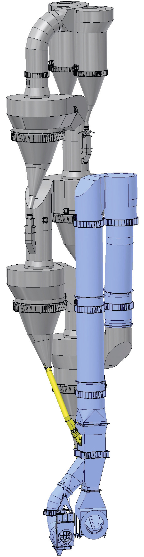
Generally, up to 60% of the thermal energy is brought into the burning process via the calciner. Unlike the kiln firing process, that of the calciner has to ensure uniform heat distribution, not the attainment of a specific highest temperature. The calciner is therefore the ideal plant section for the firing of secondary fuels. A short overview of part of the KHD Humboldt Wedag PYROCLON® calciner technology is provided in Figure 3.
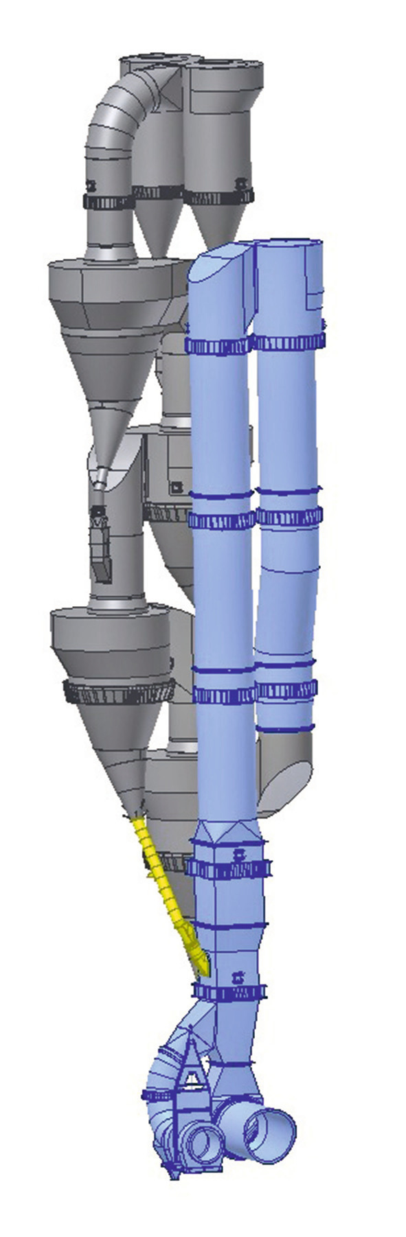
The standard version of the PYROCLON® calciner is designed for the firing of primary solid, liquid, and gaseous fuels, as well as easy-to-ignite, high-grade alternative fuels. The diameter of the calcination section is dimensioned in such a way that the obtained gas velocities allow the lifting and transportation of large-sized alternative fuels and therefore provide corresponding operational safety even in partial-load operation. The volume of the PYROCLON® calciner, i.e. cross-section and length, is decisive for the retention time and thus the burning out of the fuel. In addition, a mixing chamber called the PYROTOP® is installed at the deflection point of the calcination section. This mixing chamber ensures that the mixture of combustion air, combustion exhaust gas, residual fuel and meal are intensively post-mixed in order to ensure better fuel burnout and an effective reduction of carbon monoxide. The thorough mixing of the burning fuel is just as important as the often-mentioned retention time. It is a well-known fact that alternative fuels have a poor ignition and burnout performance. The PYROCLON® calciner can be extended to allow the use of low-grade alternative fuels and larger quantities. This provides the longer retention times needed for completion of the combustion process. To achieve primary reduction of NOx emissions when using alternative fuels, the design of the former KHD standard calciner PYROCLON® R Low NOx was refined. The advanced calciner design was designated the PYROCLON® R Low NOx AF (AF = Alternative Fuel) (Fig. 4). It operates in accordance with the well-known principle of multi-stage combustion, i.e. the feeding of fuel into a zone with a low oxygen content, before the oxygen-rich tertiary air is supplied in order to assure fuel burnout. The special feature of this design is the connection geometry of the tertiary air inlet into the calciner. This is designed so that it is impossible for meal and coarse fuel to “fall through” into the tertiary air duct and that the helical tertiary air connection creates a core flow out of the low-NOx zone of the calciner. The purpose of this is to artificially extend the NOx reduction zone before the complete mixing takes place in the PYROTOP® mixing chamber.
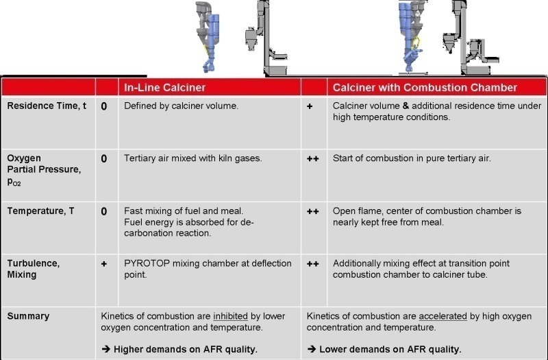
Although it is possible to burn large quantities of alternative fuels in a conventional inline calciner, the previously-described systems are limited to the low temperature range due to the immediate decarbonation reaction of the preheated meal and the low partial pressure of the oxygen due to the mixture of kiln exhaust gas and tertiary air. Both of these are parameters that limit the kinetics of the combustion reaction and thus place high demands on the quality of the alternative fuels used with regard to particle size, moisture content and calorific value.
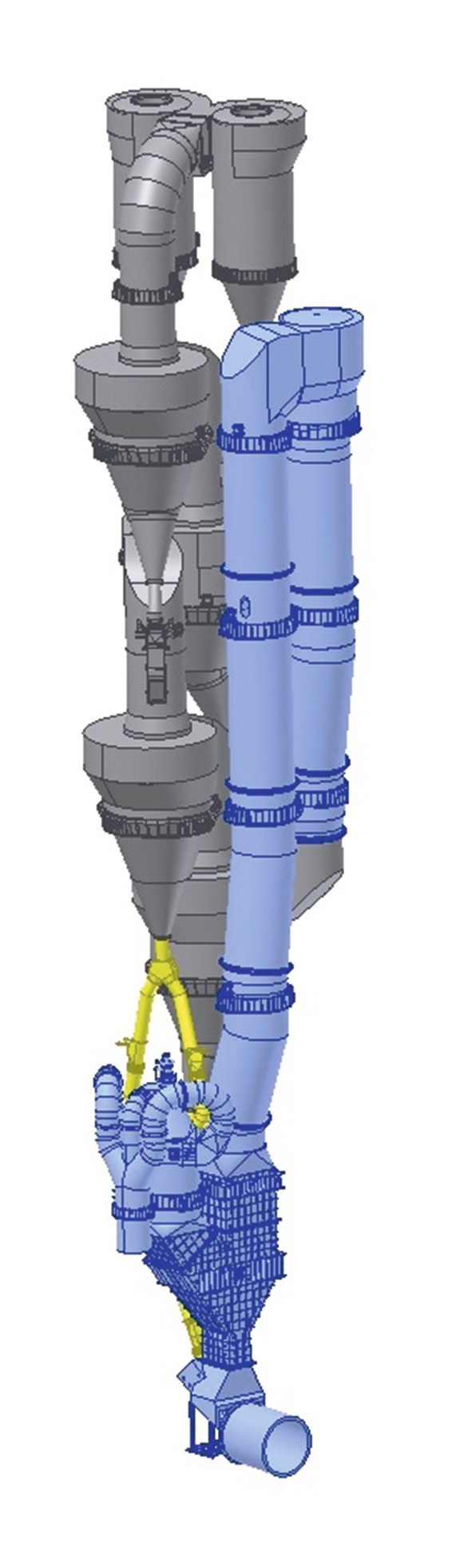
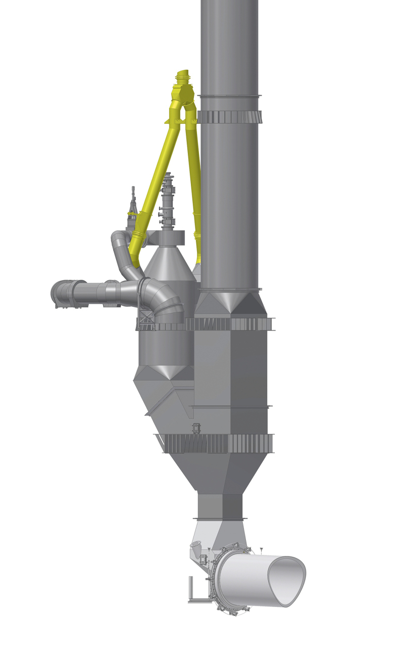
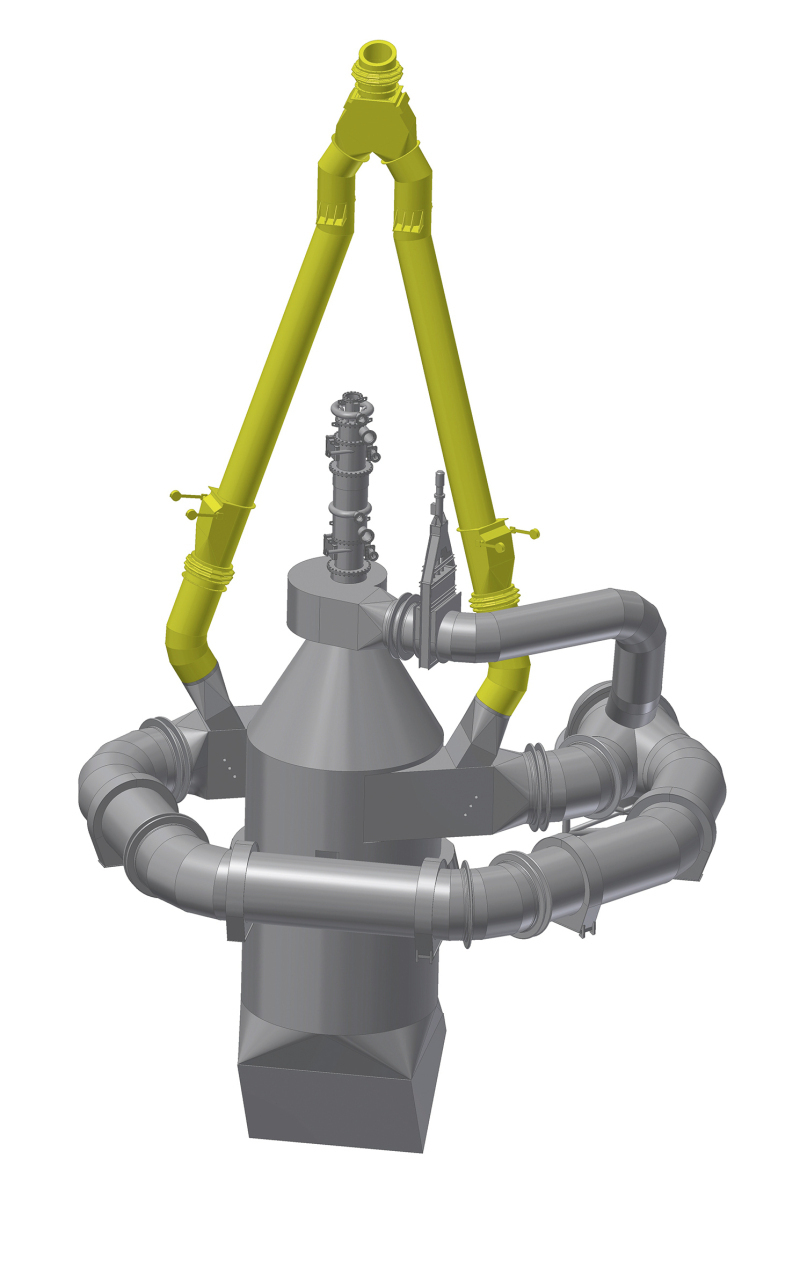
To ensure that large quantities of low-grade alternative fuels can be completely burnt out inside the calciner, the PYROCLON® R can be equipped with a combustion chamber (Fig. 5). This combustion chamber is designed to burn 100% of the calciner fuel. Therefore, there is no need for other firing points or the associated systems for supplying fuel to the calciner. Aside from the significant improvement in the firing system characteristics, the combustion chamber design also permits retrofitting for the purpose of plant modernization.
The fuel is injected into the combustion chamber via a special burner system. In contrast to conventional calciner burners, the combustion chamber burner is a multi-channel burner similar to the clinkering zone burner, provided with additional swirl air for forming and stabilising the flame. The burner is designed for the use of primary fuels and alternative fuels. An example design is shown in Figure 6. To enable the firing of coarse-grained alternative fuels, the combustion chamber burner can be equipped with a central pipe with a diameter of up to 800 mm. In addition, the burner is provided with an ignition burner that permits direct start-up of the combustion chamber without the need for hot tertiary air.
The tertiary air is fed directly into the combustion chamber dividing into three partial airstreams on the way. One partial stream is supplied as top air (initial combustion air) in the direct proximity of the combustion chamber burner, and can be actively used there for the purpose of temperature control. The two other partial streams are connected tangentially at the upper, cylindrical section of the combustion chamber. The flow of preheated kiln feed meal coming from the penultimate cyclone is split and fed to these two tangential air ducts, entering the combustion chamber radially in the tertiary air stream (Fig. 5).
The clear advantage compared to the combustion process of a conventional calciner is that - similar to the situation in a rotary kiln - the combustion takes place at a high partial pressure of the oxygen and in a zone that contains practically no meal, so that the temperatures are correspondingly high.
The high partial pressure of the oxygen results from the employment of pure, hot tertiary air in the combustion chamber. Not until the end of the combustion chamber does the almost completely burnt-out mixture blend with the gases from the rotary kiln. The high temperatures of over 1200 °C at the centre of the combustion chamber are achieved because the kiln feed meal is fed into the tangentially connected tertiary air ducts. This gives the meal a radial inlet flow path, so that it is mainly concentrated in the zone close to the combustion chamber wall. At the central core of the combustion chamber the meal concentration is low, meaning that there is a spatial demarcation between the zone of the flame and the combustion chamber wall. The energy of the hot flame at the centre of the combustion chamber is predominantly used for heating up the gas and the fuel particles, which speeds up the combustion reaction. The high concentration of meal in the zone close to the combustion chamber wall protects the refractory lining against thermal overloading. Radiation and convection heat from the flame zone is used for the decarbonation reaction, ensuring that no undesirable excessive temperatures can occur in the direct vicinity of the combustion chamber wall.
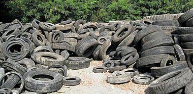
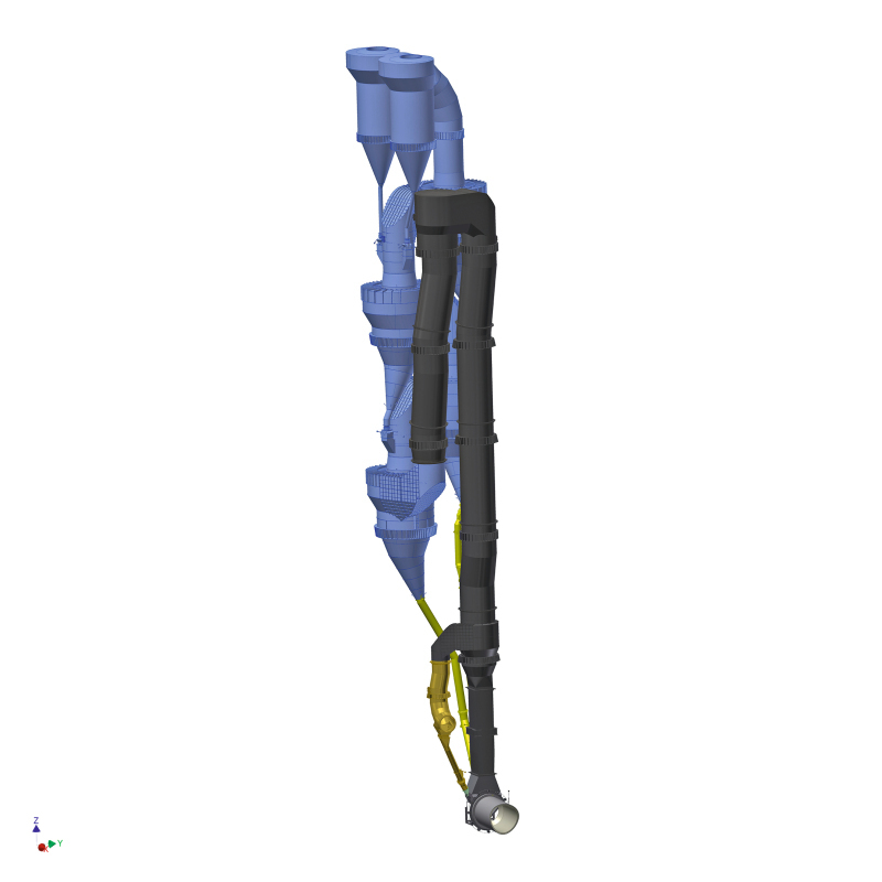
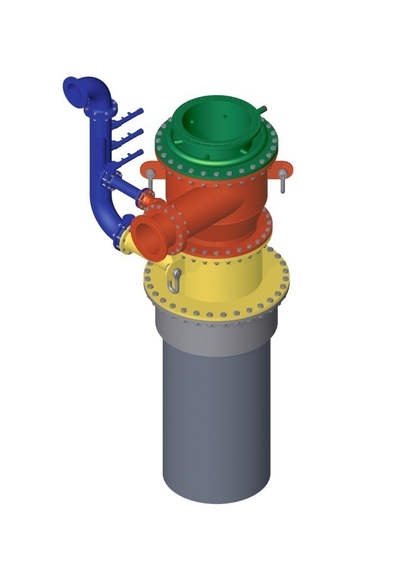
Thanks to the oxygen-rich and hot combustion atmosphere, reliable combustion of even low-grade and especially coarse alternative fuels is achieved. One of the decisive advantages of a combustion chamber (Fig. 7), is that it allows a significantly lower degree of alternative fuel preparation (particle size), which has a very beneficial effect on the cost structure for the usage of alternative fuels. Another advantage is that the combustion chamber is suitable for a significantly larger range of fuels, enabling the operator to react more flexibly to the greatly fluctuating market for alternative fuels. Meanwhile, the combustion chamber has become a recognized technology in the cement industry and is accepted as the best solution for the usage of large quantities of alternative fuels. One very interesting example from industrial practice is the KHD combustion chamber application at the Broceni cement plant of CEMEX in Latvia [2]. The clinker output of this plant is approx. 3800 tpd. Also in this plant, the main feed point of the different alternative fuels is the combustion chamber, so that there is a thermal substitution rate (TSR) of 97% in the calciner, corresponding to an absolute fuel mass flow of around 20 t/h. The remaining 3% is covered by pulverized hard coal. This process concept has the following background: the coal dosing to the calciner is deliberately kept permanently running at minimum throughput, so that if a problem is experienced with the alternative fuels (e.g. blockage or failure of the conveying system) the plant operators can react immediately.
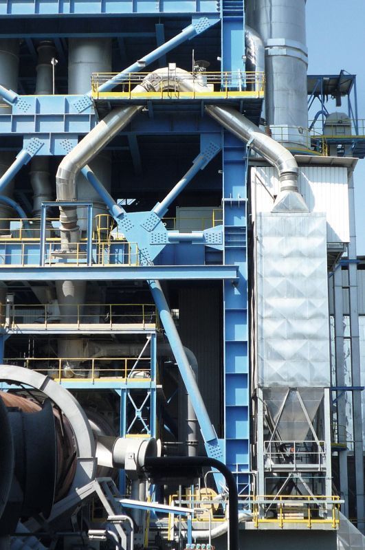
4 Kiln bypass systems
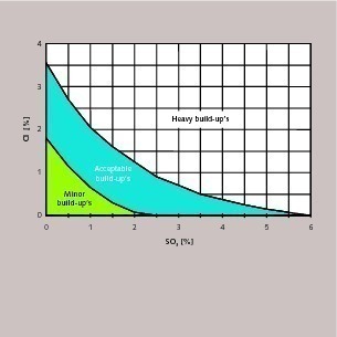
In most cases, the intake of chlorine and sulphur compounds increases when alternative fuels are used in the burning process. These two elements cause a circulation of volatile compounds in the kiln/calciner system. This circulation mainly comprises alkaline chloride and sulphate compounds that can result in increasingly thick build-ups in the zone of the kiln, calciner and lowest cyclone. Such build-ups demand constant manual cleaning of the affected zones and often lead to a decrease in clinker output, or in extreme cases to an interruption of the kiln operation.
To ensure more flexible reaction of the kiln system to the very different qualities and higher amounts of alternative fuels, it is necessary to install a kiln bypass so that a part of the circulating components in the kiln gas can be removed from the system. This interrupts the formation of the Cl and S circulation, so that the concentration of these elements measured in the hot meal can be lowered to a level where the formation of build-ups is controllable (Fig. 8). Having sold more than 70 bypass systems, KHD Humboldt Wedag has the necessary many years of experience to accurately calculate the risk potential and offer a suitable system for the specific application.
The apparent disadvantages of installing an additional bypass system with its associated energy losses are more than compensated by the advantages of a stable and consistent kiln operation. In addition to the obtained flexibility for the usage of different grades of alternative fuels, protection of the refractory lining against serious chemical corrosion and better clinker quality are two other benefits provided by a kiln bypass system.
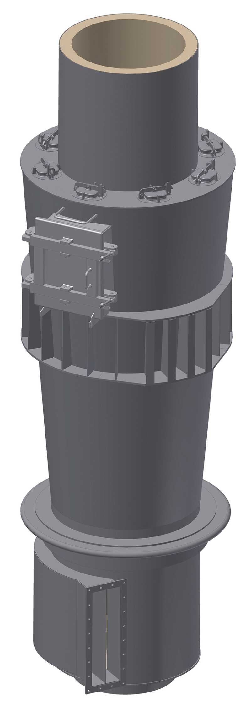
KHD Humboldt Wedag offers the engineering, including the well-proven partial gas extraction with mixing chamber and cooling air system. One of the design features of the mixing chamber (Fig. 9), is the use of internal baffle plates to force the cooling air with high turbulence into the hot kiln gas stream, resulting in extremely rapid cooling. At high bypass rates, twin fluid nozzles are installed for pre-cooling with water, in order to achieve a more efficient quenching process and a lower exhaust gas volume. The mixing chamber itself has a conical design, which provides the advantage of easier manual removal of sticky build-ups from the mixing chamber walls.
5 Handling of solid alternative fuels
The complete package for the firing of alternative fuels is rounded off by equipment for the storage, conveyance and metered feeding to the kiln system. In addition to designing the thermal process and calculating the required fuel supply rate, KHD Humboldt Wedag can also supply the complete range of equipment needed for handling the alternative fuels. For handling the generally used alternative fuels in the medium to coarser range, KHD offers a modular concept.
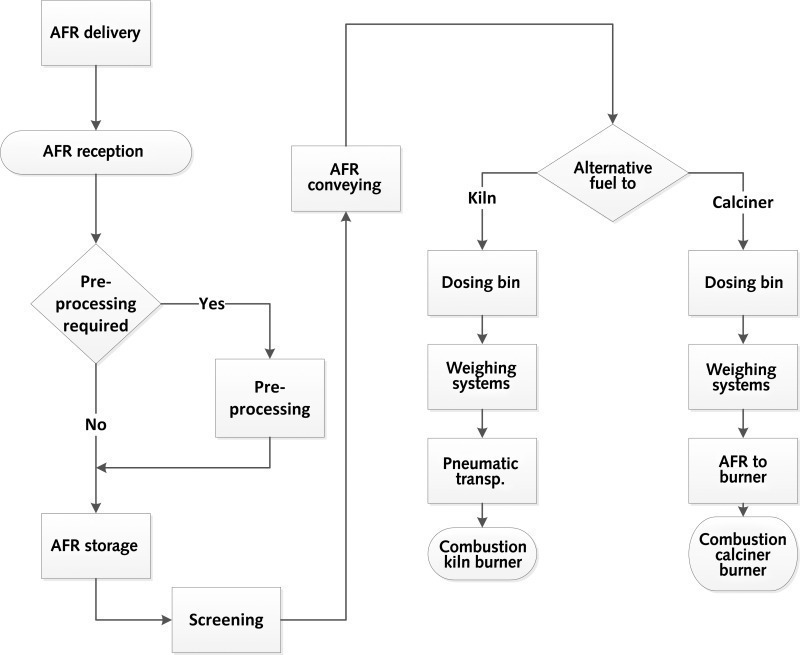
The solid fuel is delivered by truck or wheel loader to a hopper equipped with a hydraulic driven push floor. From there, the alternative solid fuel is transported to an interim storage system with a push floor or directly to the firing point. As an option, a screening system can be installed. This consists of a magnetic separator and a screen, which remove undesirable components from the flow of poorly prepared fuel. This provides the downstream machines with better protection against failure and excessive wear. Depending on the plant layout, a conveying system is chosen such that the alternative fuel can be transported from the storage location to a dosing bin located in the immediate vicinity of the firing point. This dosing bin serves as a buffer store that enables the fuel to be metered to the firing point with only a short time lag. The fuel is fed to the clinkering zone burner pneumatically, using a blow-through rotary feeder. Downstream of the metering device, the fuel feeding system for the calciner comprises a screw conveyor and chute with shut-off valve.
Using the concept described in Figure 10, different, suitably adapted module variations can be installed to deliver most of the generally used alternative solid fuels, in particular those derived from different kinds of sources (industrial or municipal wastes), as well as biomass, to the clinker burning process.
6 Summary
The usage of alternative fuels is globally accepted as a means of reducing the emission of CO2 originating from fossil fuels [1]. In addition to the environmental policy aspects involved in the usage of alternative fuels, the constantly rising prices of the increasingly scarce fossil fuels are also a factor. In most cases, the substitution of fossil fuels by alternative fuels leads to a reduction in fuel costs and thus to competitive advantages.
Alternative fuels are far less homogeneous in their chemical composition and physical properties than conventional fossil fuels. The effects of these variable compositions and properties on the clinker manufacturing process, the energy balance, the volatile impurity cycles, emissions etc. are correspondingly diverse and have to be understood and appropriately taken into account. Knowledge and experience are therefore the key to the correct planning of new plants or the conversion of existing plants in order to achieve maximum flexibility for the usage of the highest possible quantity of a broad range of alternative fuels, while ensuring consistently high quality clinker production.
To enable the implementation of such complex projects, KHD Humboldt Wedag is able to apply many years of experience in the construction of new cement plants and the modification of existing ones. In addition to the necessary analysis of all applicable raw materials and fuels, the company’s extensive database can be used to support projects and employ the entire possible range of alternative fuels. The analysis of operating data and the auditing of a plant’s current process – technological and mechanical – form the basis for top-rate process design and consequent development of possible conversion variants. The elaborated design takes particular account of the effect of the alternative fuel on clinker production, clinker quality, kiln operation and emissions. In close co-operation with the client, the profitability (i.e. the saving in fuel costs vis-à-vis the capital expenditure) can also be determined. On this basis, the complete project for the utilization of alternative fuels, from the handling up to the firing, is subsequently planned and carried out.
Überschrift Bezahlschranke (EN)
tab ZKG KOMBI EN
This is a trial offer for programming testing only. It does not entitle you to a valid subscription and is intended purely for testing purposes. Please do not follow this process.
This is a trial offer for programming testing only. It does not entitle you to a valid subscription and is intended purely for testing purposes. Please do not follow this process.
tab ZKG KOMBI Study test
This is a trial offer for programming testing only. It does not entitle you to a valid subscription and is intended purely for testing purposes. Please do not follow this process.
This is a trial offer for programming testing only. It does not entitle you to a valid subscription and is intended purely for testing purposes. Please do not follow this process.