Gas formation characteristics and inter-action during pulverized coal combustion in a precalciner environment


![10 Gas concentration distribution contours [%] and temperature contour (K) for bituminous coal combustion at Y = 0 m at 1173 K(a) CO(b) CO2(c) NOx(d) Temperature](https://www.zkg-online.info/imgs/1/3/2/7/6/7/8/Process_Xiaolin_Gas_formation_figure10a-19d2e7d912c71868.jpeg)


Pulverized coal combustion was investigated for bituminous coal and anthracite at different temperatures (973K and 1173K) in a horizontal fixed-bed reactor test system using computational fluid dynamics (CFD) software. The high temperature sufficed to promote NOx formation. For coals of identical mass, much more NOx formed during anthracite combustion than was the case for bituminous coal, but the maximum NOx concentration for bituminous-coal combustion was higher. Two experimental results are mutually complementary, providing important theoretical guidance for exploring the gaseous products of pulverized-coal combustion. Choosing anthracite as fuel and locating the coal inlets in the low-temperature zone could reduce the level of NOx emissions in the cement industry.
1 Introduction
China’s total energy consumption in 2014 was equal to 4.26 billion t of standard coal. Coal consumption accounts for more than 66 % of the total energy consumption in China, which shows that, in the process of industrialization in China, coal enjoys an unshakable status.
Coal accounts for 70 % of total energy consumption in cement production processes [1-3]. The type of precalciner used in the cement industry is a large-scale, complex chemical engineering reactor. As a high-temperature gas-solid reactor, the functions of the precalciner are gas-solid dispersion, pulverized coal...
1 Introduction
China’s total energy consumption in 2014 was equal to 4.26 billion t of standard coal. Coal consumption accounts for more than 66 % of the total energy consumption in China, which shows that, in the process of industrialization in China, coal enjoys an unshakable status.
Coal accounts for 70 % of total energy consumption in cement production processes [1-3]. The type of precalciner used in the cement industry is a large-scale, complex chemical engineering reactor. As a high-temperature gas-solid reactor, the functions of the precalciner are gas-solid dispersion, pulverized coal combustion and calcium carbonate decomposition, and pulverized coal accounts for 60 % of the cement industry’s overall energy consumption. Hence, on the premise of normal cement production, it is meaningful to study the gas release characteristics and interactions taking place during fuel combustion.
Scientists have studied pulverized coal combustion characteristics both theoretically and experimentally. Congxi Tao studied the burning intensity, the average capacity of heat release and the general burning index of 80 kinds of anthracite and bituminous coal. He found that the coal with the highest burning index, the lowest burning intensity and the highest average capacity of heat release could be rated as the best choice for precalcination in the cement industry [4]. Terry Walla et al. investigated oxygen concentration as a factor of influence on the coal burnout rate. She found that oxyfuel combustion differed from air combustion in several ways, including reduced flame temperature, delayed flame ignition and reduced NOx and SOx emissions [5]. Stanislav Honus et al. investigated the pyrolysis of gaseous components of brown coal, biomass and rubber, respectively, from 773 K to 923 K. They found that there was no distinctive linear relationship between the average abundance of CO and CO2 [6]. Song studied the NOx formation factors during coal combustion and found that the NOx yield decreased slowly with increasing temperature between 1250 K and 1750 K [7]. Michaela Perdochova et al. assessed the influence of oxygen concentration on the composition and amount of combustion products generated in the course of heating coal particles and wood sawdust at 423 K, and found that the volume of CO and CH4 decreased with decreasing oxygen concentration [8]. Masayuki Taniguchi et al. investigated the combustion of bituminous coal (1420 K – 2000 K). The results showed that the influence of temperature differed between hv-bituminous coal and sub-bituminous coal [9]. Thomas et al. studied different kinds of coal and found that, the higher the coal rank, the higher the NOx emissions yield [10].
Ultimately, the temperature and coal rank are two very important factors for pulverized coal combustion, and most previous studies focused mainly on the high and low temperature environment, while there have been only a few reports dealing with the precalciner temperature.
Until now, many scientists have conducted studies on coal combustion in a precalciner by numerical simulation with the development of computer technology [11-14]. Chao Wang researched anthracite combustion based on an HFC precalciner and found that the anthracite burnout rates of the precalciner alone and using staged combustion for the precalciner, came to 97.21 % and 97.35 %, respectively, while the corresponding rates of carbonate decomposition were 92.5 % and 93.6 %. These results were accordant with the actual condition [15]. The above studies provide important guidance for the further investigation of dynamic coal combustion in precalciners.
In a precalciner, the average temperature is about 1170 K when the exothermic reaction of coal combustion and the endothermic reaction of CaCO3 decomposition reach the state of thermodynamic equilibrium. At the CaCO3 inlets, the average temperature is lower. With increasing scarcity of energy resources, the use of coal in the cement industry is gradually shifting from bituminous coal to anthracite. Hence, it is urgently necessary to compare the combustion characteristics of bituminous coal and anthracite in the temperature environment of a precalciner. Previous scholars investigated the coal combustion process mainly by drop-tube furnace and thermogravimetric analysis [16-22]. The drop-tube furnace experiment can model the gas-solid reactions in the precalciner. However, because of the coupling effect of many factors, it is hard to deduce the exact mechanism of fuel N migration. Thermogravimetric analysis can reflect the dynamic characteristics of coal combustion, but it cannot heat rapidly. A horizontal fixed-bed reactor can model the temperature and O2 concentration in the precalciner and reflect the gas release rules both qualitatively and quantitatively. Some scholars who have performed studies based on a horizontal fixed-bed reactor focused mainly on the NOx emissions and ignored the interaction between different gas components [23-24]. Moreover, their experiment condition differs markedly from the precalciner condition.
Based on a horizontal fixed-bed reactor, this paper first investigates the combustion characteristics of bituminous coal and anthracite at 1173 K, and then studies their gaseous components at 973 K. In order to further study the dynamic combustion process, this paper builds a geometric model based on an actual precalciner and simulates the combustion of bituminous coal and anthracite suspension by means of CFD software.
2 Fixed-bed experiments section
2.1 Thermal characterizations of pulverized coal
The proximate analysis was conducted according to national standards (GB/T 212-2008). Carbon (C), oxygen (O), hydrogen (H), nitrogen (N) and sulfur (S) are the main chemical elements in a fuel. Thus, the C, H, O, N and S contents of the samples were determined by ultimate analysis conducted using a Vatio EL club analyzer. The calorific values of samples were determined with an oxygen bomb calorimeter. Each sample was tested at least three times and the results then averaged. All results were reported on the air dry basis. The proximate and ultimate analyses and calorific values of bituminous coal and anthracite are shown in Table 1. Two coals with approximately the same N contents and close calorific values are considered in this study. The time interval of sampling was 1 s. CO, CO2 and NOx of the gas yields were calculated by integration of gas curves over time according to equation (1)
mj = ∑ci × 10-6 × v ÷ 60 × t × Mj ÷ 22.4⇥ (1)
Where
mj is the CO, CO2 or NOx yield [mg]
ci is the CO, CO2 or NOx concentration [ppm]
v is the volumetric flow 1000 ml/min
Mj is the molar mass of CO, CO2 or NOx
t is the time interval of sampling 1 s
n is the number of measuring points
j is CO, CO2 or NOx
2.2 Coal combustion in a horizontal fixed-bed reactor
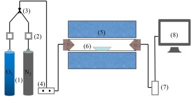
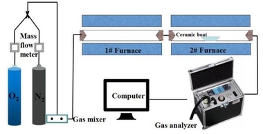
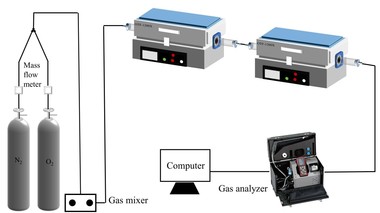
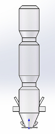
The coal combustion experimental system as shown in Figure 1 included a gas system, a tube furnace and a flue gas analyzer. The tube furnace was a type OTF-1200X employing silicon tubes as heating elements. Its adjustable temperature range extended from room temperature to 1473 K. The temperature was automatically displayed and controlled by a suitable device. N2 and O2 mixtures controlled by mass flow meters were used for combustion gases, and the O2 concentration was set at 18 %. In each experiment, the fuel sample was rapidly introduced into the quartz tube, which had already been preheated to the desired temperature with a ceramic boat. For each run, the amount of fuel sample was about 500 mg, and the gas flow rate was maintained at 1000 ml/min. The combustion gases, O2, CO2, CO and NOx were continuously monitored by an MGA5 flue gas analyzer. The device measured the concentrations of O2 and CO2 gases with an infrared (IR) cell as volume percentages; concentrations of other gases were measured electrochemically in ppm.
2.3 Coal combustion results and discussion
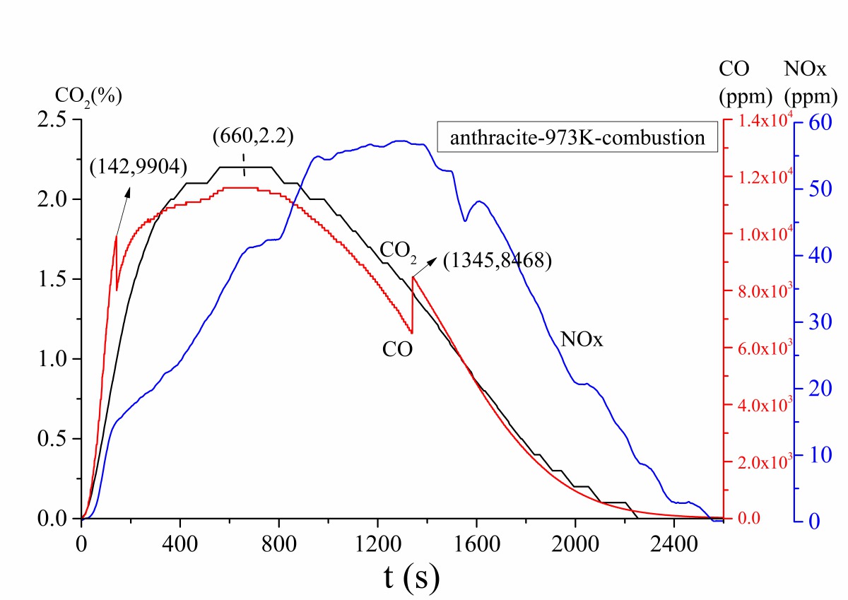
Figure 2a is the gas release curve of bituminous coal combustion at 1173 K. Figure 2b is the gas release rate curve, which is the derivative curve of Figure 2a. Figure 3 shows the gas release curve of bituminous coal pyrolysis at 1173 K. Figure 4 is the gas release curve of bituminous coal combustion at 973 K. Figure 5 depicts the gas release curves of anthracite combustion at different temperatures 1173 K (Figure 5a) and 973 K (Figure 5b). The CO, CO2 and NOx yields (as shown in Table 2) during combustion at different temperatures were calculated by the integration of gas curves over time according to formula 1. Table 3 shows the gaseous components’ maximum values during combustion.
As shown in Figure 2a, the bituminous coal combustion product was mainly CO2, and the release peak was 4.98 %. The amount of CO and NOx were relatively low, with peaks situated at 198 ppm and 136 ppm, respectively. According to Figure 2a and 2b, the bituminous coal combustion process can be classified into four stages. The first stage was the early combustion (0 s < t < 82 s), which included the volatile release and combustion process. At this stage, the CO, CO2 and NOx generated gradually, and their release peaks formed gradually. According to Figure 3, the release peaks derived from the initial pyrolysis products. Among them, the CO released rapidly and formed a release peak (t = 60 s). The CO peak was the sharpest, showing that the CO formation reaction was the fastest. The CO2 release start point was later than the CO curve, and the CO2 peak also formed later and was wider than CO peak. The NOx release start point was the latest, and the formation rate was the slowest, demonstrating that the NOx formation reaction was the slowest. The second stage was the char ignition combustion stage (82 s < t < 196 s). In this stage, the CO concentration decreased continually (Figure 2a), but the absolute value of the CO release rate continued to increase, because part of char began to burn and form CO at this stage, hence keeping the CO concentration from decreasing. At this stage, CO2 formation began at t = 101 s, which was later than the time needed for CO formation (t = 82 s). NOx formation continued from 82 s < t < 111 s, which shows that the volatile NOx formation reaction was less readily achieved than the CO and CO2 formation reactions. At 111 s < t < 158 s, the NOx formation rate decreased gradually. After that, i.e. between 158 s < t < 196 s, the NOx formation rate remained stable. The third stage was the char stable combustion stage (196 s < t < 918 s). In this stage, the CO formation concentration was very low, the average concentration being about 18 ppm. There was a small peak at t = 918 s on the CO formation curve. This may have been caused by materials pyrolysis, as shown in Figure 3. The CO2 formation rate remained stable, and there was a small CO2 formation peak at t = 491 s. The char NOx began to generate after t = 491 s. The fourth stage was the later char combustion stage (t > 918 s). In this stage, both CO and CO2 concentration decreased rapidly, NOx concentration decreased relatively late (t > 956 s). The CO formation reaction ceased at t = 1421 s, the CO2 formation reaction at t = 1681 s, and the NOx formation reaction at t = 1900 s (Figure 2a). During the entire combustion process, CO formed more readily than CO2 and NOx.
According to Figures 2 and 4, when the combustion temperature decreased from 1173 K to 973 K, some differences were noted between the individual gas release curves. Firstly, there was no obvious boundary between volatile combustion and char combustion at 973 K, i.e. it was blended combustion. Secondly, the starting points, peak points, gas release rates and terminal points for CO, CO2 and NOx occurred later at 973 K, which showed that the combustion rate was slower and the combustion process longer at a lower temperature. Thirdly, as shown in Table 2, the CO formation yield increased from 0.65 mg to 241.05 mg when the combustion temperature decreased from 1173 K to 973 K, while both the CO2 and the NOx formation yields decreased. The above comparison of results revealed that the lower temperature combustion environment was conducive to CO formation, which in turn could inhibit the NOx formation reaction.
Considering Figure 2, Figure 5a and Table 2 together, according to the CO curves, the anthracite combustion process at 1173 K also included four stages: a volatile release and combustion stage, a char ignition combustion stage, a char stable combustion stage, and a late char combustion stage. During the volatile release and combustion stage, there were no CO2 and NOx release peaks, since the anthracite contained less volatile material, as shown in Table 1. For anthracite, the char stable combustion process was about 1170 s (Figure 5a, 180 s < t < 1350 s), which was longer than the bituminous char stable combustion stage (Figure 2a, 196 s < t < 918 s, about 722 s). This is because the anthracite contained much more fixed carbon. During the char stable combustion process, the CO2 peak point for anthracite was 3.1 %, while for bituminous coal it was 3.5 %, showing that the anthracite was less easy to burn in comparison with bituminous coal. The terminal points for CO and CO2 were t = 2346 s and t = 2556 s, respectively, during anthracite combustion, while for bituminous coal combustion, they were t = 1421 s and t = 1681 s, respectively. So complete anthracite combustion of the same mass took longer than for bituminous coal. Compared with the NOx curves, the NOx formation yield was lower during the volatile release and combustion process for anthracite, whole there was a large amount of NOx formation during the char combustion process. Therefore, most of the NOx were char NOx during anthracite combustion, and the NOx formation yield for anthracite combustion was much higher than during bituminous coal combustion (Table 2).
According to Figures 5a and 5b, when the anthracite combustion temperature decreased from 1173 K to 973 K, the gas release rules were similar to those governing bituminous coal combustion. As shown in Table 2, the CO formation yield increased from 0.74 mg to 327.08 mg when the combustion temperature decreased from 1173 K to 973 K; conversely, both the CO2 and the NOx formation yield decreased.
Analysis of the gas release rules during two kinds of coal combustion, bituminous coal and anthracite, at 973 K, combined with Figure 4, Figure 5b, and Table 2. For anthracite, the CO and NOx formation yields were lower in the volatile release and combustion stage than in the char combustion stage. The CO and NOx formation yields for anthracite combustion were much higher than for bituminous coal combustion (Table 2). The CO2 curve tendency of anthracite combustion was similar to that of bituminous coal. At 973 K, the both kinds of coal required the same length of time for burning completely.
3 Numerical simulation section
3.1 Geometrical models
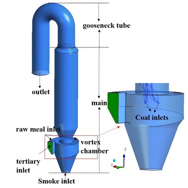
Figure 6 is a schematic diagram of the precalciner with swirl chamber. The flue-gas enters into the precalciner from the bottom, the tertiary air inlet is at the side of the body, and the tertiary air enters into the swirl chamber in the tangential direction. The tertiary air inlet is set at the bottom of the precalciner, which combines with the flue-gas to enhance the mixing effect on the materials. The swirl chamber can effectively prolong the residence time of fluids. The raw meal inlets are just above the swirl chamber. The pulverized coal is injected into the precalciner as shown in Figure 6. The gooseneck structure can promote coal combustion and calcium carbonate decomposition. A hexahedral cell is used to mesh the complete precalciner, and grid refinement is adopted in the swirl chamber. The whole mesh is made up of 137 865 nodes.
3.2 Boundary conditions
The structural parameters and boundary conditions are shown in Table 3. The parameters were observed as such at the cement plant. All inlets are velocity inlets, and the outlet is a pressure outlet. Parts other than the bottom of the flue-gas inlet, the tertiary air inlet, the two raw meal inlets and the top outlet, are regarded as a wall and therefore simulated with standard wall functions.
3.3 Mathematical models and numerical solutions
The precalciner structure was simplified in order to study the pulverized coal combustion characteristics with Fluent software. The following assumptions were made to simplify the modeling:
1) The temperature and velocity field are in a stable state
2) The gases are continuous-phase
3) The entire wall surface is smooth
4) Regardless of the thermal NOx and prompt NOx, only the fuel NOx is considered
In an Euler coordinate system, the gas phase was expressed with the realizable k-ε two-equation model, because that model provided the best performance of separated flows and flows with complex secondary flow features. In a Lagrange coordinate system, the solid phase was expressed with the discrete phase model (DPM). The physical model is two-way turbulence coupling, which can enable the effect of change in turbulent quantities due to particle damping and turbulence eddies. Coal particles following the Rossin-Rammler size distribution are tracked using a stochastic trajectories model, and the gravity effect is taken into account. The devolatilization model is a single-rate model, which assumes that the rate of devolatilization is first-order dependent on the amount of volatile remaining in the particle. The chemical reactions of combustion and decomposition are expressed with a species transport model and a finite-rate/eddy-dissipation model, respectively. The phase-coupled SIMPLE method is used for pressure-velocity coupling of the Euler model. A first-order upwind scheme is employed for the other items of equations. The equations are solved according to the face-face iterative TDMA (tridiagonal matrix algorithm) method. The convergence criterion for energy is less than 10-6, and the other residuals are less than 10-3.
3.4 Numerical simulation results and discussion
Figures 7a and 7b show the streamline of gas flow and the pulverized coal particles trajectory. It was obvious that the gas flow would rise spirally after being injected into the precalciner. The circular streamline was at large scale in the swirl chamber. This kind of movement shows that the precalciner has a good overall vortex effect, which can prolong the residence time and improve the dispersion effect of particles. Combining the streamline with the pulverized coal particles trajectory revealed that the particles moved with the gas-flow. The pulverized coal combustion process distributed mainly above the swirl chamber.
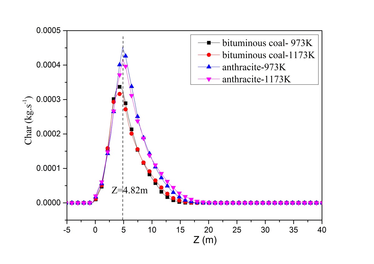
In order to correspond with the tube experiments, the tertiary air was set at 1173 K and 973 K. Bituminous coal combustion and anthracite combustion were modeled. Figure 8 is the devolatilization contour (a) and the char burnout rate contour (b) for bituminous coal combustion with a tertiary air temperature of 1173 K. Figure 9 depicts the average devolatilization curve and the char burnout rate curve of bituminous coal combustion for a tertiary air temperature of 1173 K. According to Figures 8 and 9, the first-released volatiles burned quickly (-2 m < Z < 2.18 m) after being injected immediately above the swirl chamber. The char began to burn at Z = -0.44 m, the combustion reaction was violent at Z = 4.82 m, and the reaction ceased at about Z = 17.45 m. The numerical simulation of bituminous coal combustion showed that combustion included two stages: volatile release and combustion, and char combustion. There was an overlapped area for the two stages. This pulverized coal combustion process in the precalciner was consistent with static combustion in the tube, which demonstrated the rationality of the simulation results.
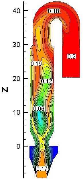
Figure 10 represents the gas concentration distribution contours and temperature contour for bituminous coal combustion at Y = 0 m and a tertiary air temperature of 1173 K. Figure 11 shows the gas average concentration distribution and average temperature curves for bituminous coal combustion at 1173 K on cross slices along z direction.
The CO release began at Z = -0.7 m (Figure 11), and the CO concentration first increased and then decreased (Z > 10.15 m), because the char combustion rate was low at Z > 10.15, and CO was continually oxidizing into CO2. At Z < -0.7 m, most of the CO2 came from the flue gas. At Z > -0.7 m, the CO2 derived primarily from pulverized coal combustion. By contrasting the distribution of CO and CO2 in the precalciner according to Figures 10a
and 10b, it was found that the CO concentration in the middle part was higher, while the CO2 concentration was lower there. This is because the CO2 came from char combustion and the CO had been oxidized. In the middle part of the precalciner, the O2 concentration was lower, and less CO was oxidized, so the CO2 concentration was lower there. As to be seen in Figure 10c, the fuel NOx distribution was similar to the CO distribution, but the high NOx concentration zone came later than the high CO concentration zone, documenting that the NOx formation reaction was less readily achieved than the CO formation reaction. According to Figure 10d, at -9.8 m < Z < -0.7 m, the average temperature decreased gradually, because the temperature of the flue gas was higher than the temperature of the tertiary air. In the main part of the precalciner, the average temperature increased gradually with the burning of pulverized coal. A low-temperature zone located at Z = 0 m resulted from pulverized coal being injected into that part of the precalciner, and the pulverized coal having absorbed the heat from the gas flow.
Figures 12 to 17 show the average values of the various parameters on cross slices along the Z direction in four conditions. Figure 12 relates the average velocity distribution curves. When the tertiary temperature was 1173 K, the average velocity at different heights was lower, because at any higher temperature, the combustion rate was also higher, the coal residence time shorter, and the gas-solid interactions weaker.
Figure 13 consists of the average volatile combustion rate (a) and char combustion rate (b) curves, respectively, on cross slices along the Z direction. Figure 14 lays out the average temperature curves on cross slices along the Z direction under four conditions. The bituminous coal contained much more volatiles than did the anthracite, and the volatiles combustion rate was higher, resulting in a higher average temperature in the earlier stage (-0.7 m < Z < 21 m at 1173 K, -0.7 m < Z < 18.8 m at 973 K). Part of the anthracite burned in the upper part of the precalciner, producing a higher average temperature (Z > 21 m at 1173 K, Z > 18.8 m at 973 K). The char combustion rate for different coals was fluctuant, possibly due to the velocity (Figure 12).
Figures 15 and 16 are CO and CO2 average concentration curves on cross slices along the Z direction under four conditions. In the earlier combustion process (-0.7 m < Z < 3.6 m), the CO and CO2 average concentrations of bituminous coal combustion were higher than for anthracite combustion. With char combustion, the CO average concentration of anthracite combustion was higher than for bituminous coal combustion, and the CO2 average concentrations grew closer together for different coal combustions. For bituminous coal and anthracite, the CO formation yield was higher for a tertiary air temperature of 1173 K. This is because, at a tertiary air temperature of 1173 K, the temperature at Z >8 m exceeded 1900 K, and carbon can be oxidized into CO at such a high temperature.
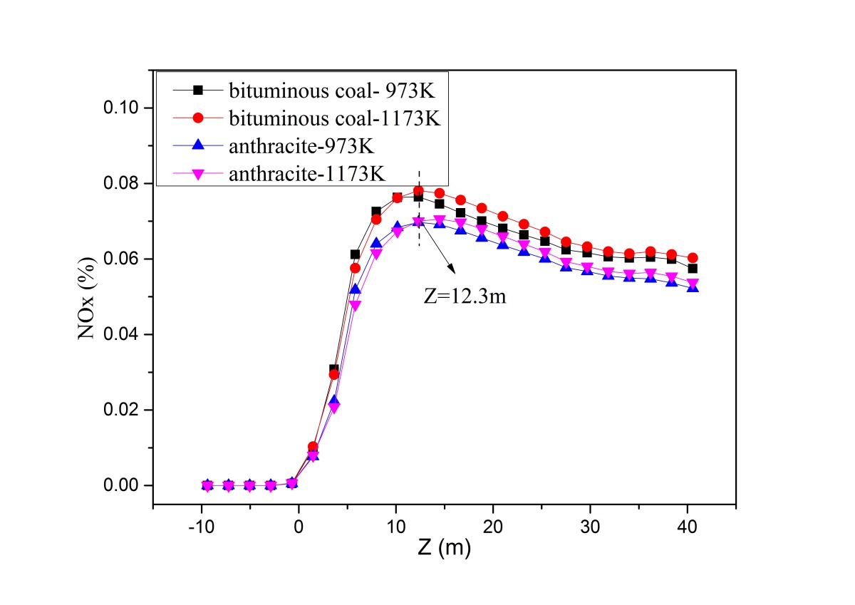
Figure 17 displays the NOx average concentration curves on cross slices along the Z direction under four conditions. At Z < 12.3 m, bituminous coal combustion yielded much more NOx, since the bituminous coal contained much more volatiles. At Z > 8 m, the char burned and formed a large amount of char NOx, hence reducing the NOx concentration gap between the two kinds of coal. According to Figure 17, much more NOx formed during bituminous coal combustion, and much more NOx formed when the temperature was higher. In the fixed-bed experiment, the NOx concentration maximum was 136 ppm and 105 ppm, respectively, at 1173 K and 973 K during bituminous coal combustion and 100 ppm and 60 ppm, respectively, at 1173 K and 973 K during anthracite combustion. Thus, the numerical simulation results were consistent with fixed-bed experiment results.
It is important to note that the numerical simulation of pulverized coal combustion belongs to the macrodynamic experiment category, involving a large quantity of pulverized coal and a very high temperature in the precalciner. However, the tube furnace combustion experiment is a small static experiment with a smaller quantity of pulverized coal involved. At high temperature (1173 K), the flue gas analyzer detected a small amount of CO. Although the CO was generated very quickly, its conversion reaction was also very quick. So, some of the phenomena differ between the two methods during pulverized coal combustion. It is therefore necessary to combine the two methods to allow a reasonable judgment concerning pulverized coal combustion.
4 Conclusions
(1) In the tube furnace experiments, at 1173 K, the combustion process included two main stages: volatile release and combustion, and char combustion. With blended combustion taking place at 973 K, the combustion reaction was slower, and a large amount of CO formed that could not be oxidized into CO2, a fact that can inhibit the formation of fuel NOx.
(2) In the tube furnace experiments, at 1173 K, during volatile combustion, there was merely a CO release peak, but no CO2 or NOx release peaks for anthracite, while CO, CO2 and NOx release peaks for bituminous coal were observed during char combustion. The anthracite char steady combustion time was longer than for bituminous coal; CO and NOx formed mainly during the char combustion process for anthracite, and their yields were higher than for bituminous coal combustion at the same temperature.
(3) The numerical simulation results showed that the pulverized coal moved with gas flow, and that the volatile released first and burned quickly, during which the char also began to burn. CO and CO2 formed primarily in the main part of the precalciner, and NOx formed in both the volatile combustion stage and the char combustion stage.
(4) The numerical simulation results showed that, when the tertiary air temperature was 1173 K, the CO formation yield and char NOx formation yield were much higher than at 973 K.
(5) The results of numerical simulation showed that, in the earlier combustion stage, the CO and CO2 concentrations were higher for the bituminous coal, since the bituminous coal contained a large amount of volatiles. In the later combustion stage, the CO concentration during anthracite combustion was higher than during bituminous coal combustion; the CO2 concentrations grew closer together for different coal combustions, and much char NOx formed at this stage.
(6) The high temperature was seen to promote NOx formation. For coals of equal mass, much more NOx formed during anthracite combustion as compared to bituminous coal, despite the fact that the NOx concentration maximum for bituminous coal combustion was higher.
Acknowledgements
This work was financially supported by the National Natural Science Foundation of China (51502221).
Überschrift Bezahlschranke (EN)
tab ZKG KOMBI EN
This is a trial offer for programming testing only. It does not entitle you to a valid subscription and is intended purely for testing purposes. Please do not follow this process.
This is a trial offer for programming testing only. It does not entitle you to a valid subscription and is intended purely for testing purposes. Please do not follow this process.
tab ZKG KOMBI Study test
This is a trial offer for programming testing only. It does not entitle you to a valid subscription and is intended purely for testing purposes. Please do not follow this process.
This is a trial offer for programming testing only. It does not entitle you to a valid subscription and is intended purely for testing purposes. Please do not follow this process.