Simulation of limestone calcination in normal shaft kilns – mathematical model
The process of calcination in normal shaft kilns can be described and simulated by means of a mathematical model in which the operating conditions, material properties and kiln geometry serve as variables. The results can be used for purposes of process optimization, kiln design and personnel training.
1 Introduction
Lime burning, i.e., the calcination of limestone, is a very complex process, because it involves numerous significant parameters – including:
the operating conditions (throughput, fuel quantity, combustion air quantity, fuel type and composition, ambient temperature, air speed),
the kiln geometry (diameter, height of solid bed, length of cooling zone, thickness of wall layers) and
the characteristics of the stone (average size, particle size distribution, calcite component, magnesite component, thermal conductivity, reactivity, moisture content)
Due to the large number of parameters,...
1 Introduction
Lime burning, i.e., the calcination of limestone, is a very complex process, because it involves numerous significant parameters – including:
the operating conditions (throughput, fuel quantity, combustion air quantity, fuel type and composition, ambient temperature, air speed),
the kiln geometry (diameter, height of solid bed, length of cooling zone, thickness of wall layers) and
the characteristics of the stone (average size, particle size distribution, calcite component, magnesite component, thermal conductivity, reactivity, moisture content)
Due to the large number of parameters, an empirical approach to optimizing the process or designing a suitable kiln would be very difficult. For one thing, the kiln reacts so sluggishly, that any change in parameters would take days to become noticeable. For another, continuous measurements are very difficult to perform in a sinking solid-stone bed. Ascertainment of axial temperature profiles is of limited usefulness, because Ni-Cr-Ni thermocouples (type K) break down at temperatures beyond 1300 °C. Pt-Rh thermocouples (type S) can better cope with such temperatures, but they are prohibitively expensive. Consequently, a mathematical model was developed to simulate the entire in-kiln process.
The model essentially comprises a system of ordinary differential equations based on energy and mass balances, coupled with a discrete reaction model based on the core-shell model. Along with the calculation of axial particle- and gas-temperature profiles and the time history of decomposition, the wall losses and the pressure loss are determined, as well. A combustion calculation based on mole balances was also implemented in the process model to enable determination of the exhaust-gas composition. A similar model has already been presented for PFR-type kilns (Parallel-Flow Regenerative).
The generation of a stable resolution algorithm was very time-consuming and complicated, because the position of the decomposition zone had to be re-established for each change of parameters. The finished program calculates the axial profiles of the surface and core temperatures of the limestone, as well as of the gas temperature and limestone decomposition. This data then serves as the basis for calculating the specific energy consumption, the residual CO2 content, the exit temperature of the lime, the exhaust-gas composition (wet and dry), the exhaust-gas temperature, the pressure loss and the wall losses. The effects of all aforementioned parameters can be simulated. All results are output both in chart form and as Excel tables. The program is intuitively structured for rapid application in the field. It offers economic benefits deriving from optimization of the calcining process in terms of energy consumption and product quality for changes in throughput, type of fuel, fuel composition and limestone properties, as well as for the training of personnel.
The mathematical model itself and the effects of several different parameters on the lime-burning kiln process are described below.
2 Modelling
2.1 Postulates
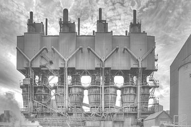
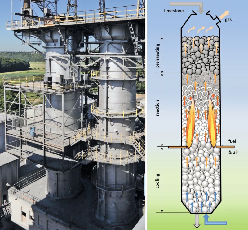
The leading image of this article shows a photograph plus a schematic diagram of a normal shaft kiln. For modelling purposes, it is assumed that the fuel and secondary air are introduced at a single level, that they are evenly distributed over the cross section of the kiln, and that the flow pattern is uniform. Accordingly, the temperature of the gas and stone fill can be assumed as uniform over the cross-sectional area of the kiln, and the conversion rate is likewise uniform. The actual distribution of fuel within the cross section is still unknown and is presently the subject of investigation of an AiF research project.
A steady-state in-kiln process is postulated. For the sake of simplicity, the particles of limestone are assumed to be spherical.
2.2 Energy balance
The axial temperature profile of the gas derives from the differential energy balance of a length element dz
d dz [M ˙ g(z) · cp,g(z) · Tg(z)] = dM ˙ f(z) dz hu – a(z) · AF · O · (1– c)
[Tg(z) – Tsw(z)] – dQ ˙ w(z) dz .⇥(1)
The change in the enthalpy flow of gas is equal to the amount of heat generated by combustion of the fuel, the heat transferred to the solid by the gas, plus the local wall heat losses. In this equation, M ˙ g is the mass flow, cp,g the specific heat capacity of the gas, Tg the temperature of the gas, M ˙ f the mass flow of fuel, hu the net calorific value of the fuel, a (h) the heat transfer coefficient, AF the internal cross-sectional area of the kiln, O the specific surface area of the stone, expressed as m2/m³ (6/d for spheres), c the void fraction of the solid bed, Tsw the surface temperature of the particles and Q ˙ w the local loss heat flow through the wall of the kiln. The heat of combustion in the preheating and cooling zones is therefore, by definition, zero.
The differential energy balance for the solid reads:
d dz [M ˙ g(z) · cp,g(z) · Tg(z)] = a(z) · AF · O · (1– c) ·
[Tg(z) – Tsw(z)] – M ˙ CO2,t · dX(z) dz · DhCO2.⇥(2)
The change in the enthalpy flow of the solid is equal to the amount of heat transferred to the solid by the gas plus the enthalpy required for decomposition. In this equation, M ˙ s is the mass flow, cp,s the specific heat capacity, Ts the mean temperature and Tsw the surface temperature of the particles, M ˙ CO2,t the entire mass flow of CO2 through the limestone, dX(z) the local change in the limestone conversion rate and DhCO2 the enthalpy of limestone decomposition. The infeed temperatures Tg,z=L and Ts,z=0 at the front of the kiln are stated as initial conditions.
2.3 Mass balance
The mass flow of gas consists of the fuel, the combustion air and the generated carbon dioxide:
M ˙ g(z)= M ˙ f + M ˙ a + M ˙ CO2,t · X(z) = (1 + l · L) · M ˙ f + M ˙ CO2,t · X(z).⇥(3)
where
M ˙ CO2,t = M ˙ 1s · YCO2.⇥(4)
In these equations, M ˙ a is the mass flow of air, M ˙ ls the mass flow of dry limestone passing through the top of the kiln, X(z) the local limestone conversion rate, YCO2 the mass fraction of carbon dioxide in the infed limestone, L the stoichiometric air requirement and l the excess air number (fuel/air mass ratio). In the cooling zone, the mass flow of gas consists only of cooling air. The mass flow of solid material diminishes due to decomposition according to:
M ˙ s(z) = M ˙ 1s · (1– X(z) · YCO2).⇥(5)
2.4 Heat transfer
Convective heat transfer is calculated according to the Nusselt equation [1, 2]
Nu = 2 + 1.12 · Re0.5 · Pr0.33 · (1– c c ) + 0.005 Re⇥(6)
where the dimensionless numbers are defined as follows:
Nu = a · d lg , Re = w · d c · v, Pr = v __ a ⇥(7)
In those equations, d is the mean diameter of the stone and lg the thermal conductivity of the gas. The velocity is the superficial velocity of the volume related to the free cross section. Both this parameter and the material properties are temperature-dependent and fluctuate with the composition of the gas (due to decomposition and combustion reactions) and the excess air number x.
Carbon-dioxide gas radiation accounts for less than 10 % of the overall rate of heat transmission. Consequently, that factor is not explored any further for calculatory purposes. Instead, reference is made to [3]. Steam radiation is negligible.
In the preheating and cooling zones, transient heat conduction into the stone is accounted for by the transient factor
1 = 1 + d/2 ,⇥(8)
ages a x · ls
where x = 5 for spheres and ls is the thermal conductivity of the stone.
2.5 Limestone decomposition
As is generally known, limestone decomposes in line with the inwardly migrating reaction front and can therefore be described by the core-shell model [4, 5]. For thermal conduction through the outer lime layer of a hollow sphere is valid
Q ˙ = 2p · rif · d · ll (d/2 – rif) · (Tsw – Tif).⇥(9)
where rf is the radius of the reaction front, Tif the temperature of the reaction front as well as the core temperature, and ll the thermal conductivity of the lime. The heat flow is carried off with the CO2 as reaction enthalpy
Q ˙ = M ˙ CO2 · DhCO2.⇥(10)
Transport of the carbon dioxide is determined by the chemical reaction, pore diffusion and mass transfer
1 pif p`
M ˙ CO2 = 2p · rif · d · 1 + d/2 – rif + 1 · (RCO2· Tif – RCO2· Tg)⇥. (11)
k DP b
where k is the coefficient of reaction, DP the coefficient of pore diffusion, b the coefficient of mass transfer, RCO2 the gas constant of CO2, p` the partial pressure of CO2 in the gas and pif the equilibrium pressure. The resultant local change in conversion rate is described by
d 1 · M ˙ CO2 = (1 – c) · AF · 6 M ˙ CO2
dzX(z) =ws p · d3 · rs · YCO2 p · d3 · M ˙ 1s· YCO2⇥
6 ⇥ (12)
where ws is the velocity and rs the density of the solid material.
The equilibrium is pressure pif is
pif = p0 · exp (– DHR R · Tif)⇥(13)
where p0 is the maximum pressure with the value 2.15 × 10⁷ bar and DHR the enthalpy of decomposition with the value 168 kJ/mol. The equilibrium pressure and the enthalpy of decomposition are slightly dependent on the nature of the limestone [6] and [7]. The coefficients of reaction and pore diffusion are also mild functions of the type of limestone [4] and [5]. Both material properties influence the level of the decomposition temperature. Their impact on the duration of decomposition, however, is minor. The latter is largely determined by the thermal conductivity of the lime. Since that value can vary by a factor of two between types of lime, this material properties exert a crucial influence on decomposition time. The mathematical model can be used to simulate the effects of all material properties.
3 Results of simulation
3.1 Temperature profiles and degree of conversion
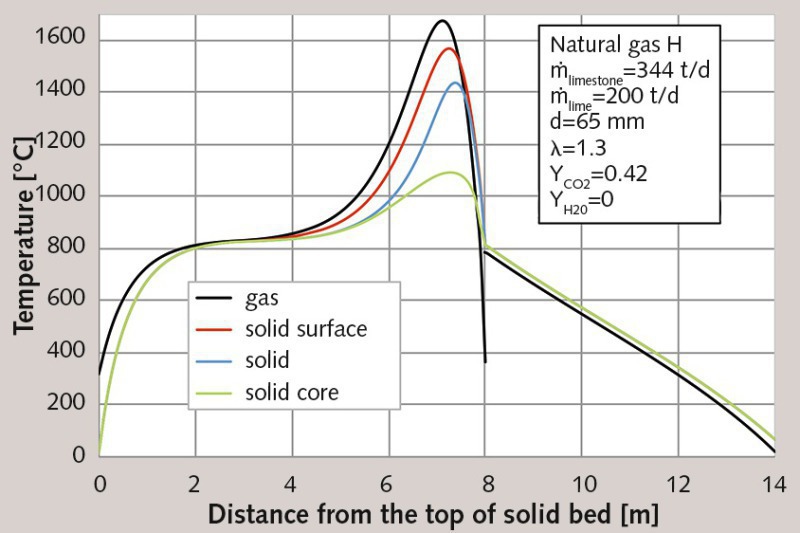
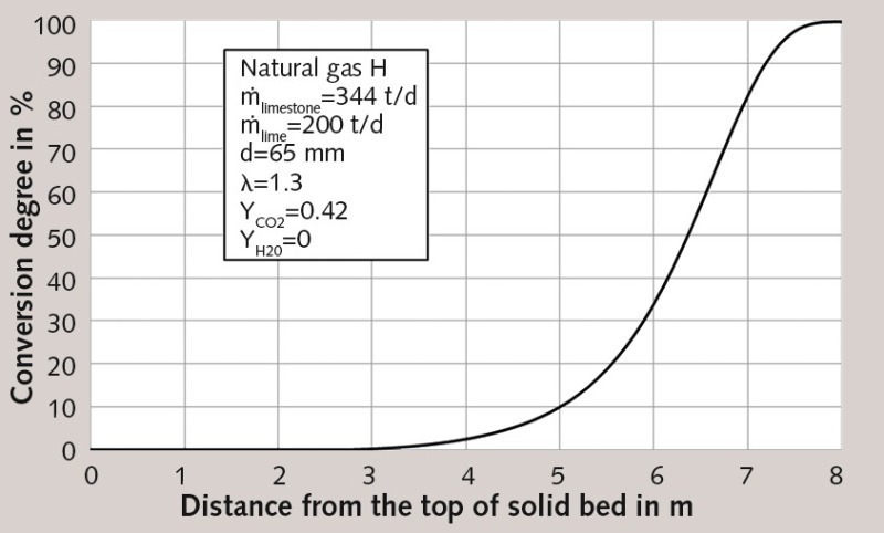
The potential results of simulation are explained below by way of example. The kiln has a diameter of 2.5 m and a total solid-bed height of 14 m, including a 6-meter cooling zone. Its limestone throughput amounts to 344 t/d. The limestone is presumed dry. It should be noted that the moisture content of the limestone has no effect on the in-kiln process, but only lowers the exhaust-gas temperature at the top end of the kiln. The mean particle size is assumed to be 65 mm. The limestone contains 42 % CO2 (weight loss). The injected fuel is natural gas with a net calorific value of 37.4 MJ/Nm³. The volume flow of fuel stands at 860 Nm3/h, yielding a burner output of 8.92 MW. In addition, an excess air number of 1.3 is assumed, so the volume flow of air figures to 11100 Nm3/h.
Within the cooling zone, the mean heat capacity flow ratio between limestone and air is postulated as 1.0. This capacity flow ratio reflects the minimum value for cooling air. The rest of the required combustion air is introduced with the fuel. This helps distribute the fuel more uniformly over the cross-sectional area. Table 1 summarizes the values assumed for the simulation.
Figure 1 shows the calculated temperature profiles of the gas, of the solid surface, of the solid core and the mean temperature of the particles along the vertical axis of the kiln. For better understanding, the horizontal axis depicts the vertical direction. The coordinate 0 m indicates the top of the solid bed. The limestone is filled into the kiln from the top at an ambient temperature of 10 °C. Passing through the next 2.5 m, it is heated to decomposition temperature (in this case 830°C). This marks the beginning of the S-shaped conversion curve shown in Figure 2. The conversion process comes to an end after approx. 7.8 m, when the residual CO2 content amounts to 0.3 %. Just before the end of the conversion process, the temperatures are at their highest, as reflected in Table 2. Accordingly, the surface of the solid material reaches a temperature of 1560 °C, while the core temperature peaks at approximately 1080 °C. This denotes a very large temperature differential between surface and core. At a temperature of approximately 800 °C, the lime enters the cooling zone, where it is cooled to 67 °C by cooling air entering the kiln at a temperature of 20 °C.
Due to extensive convective heat transfer, the temperatures difference between air and limestone are relatively small. In view of the fact that the capacity flow ratio is equal to one, the temperature curve is nearly linear. The slight deviation from linear is attributable to the temperature dependence of the material property and, hence, of the heat transfer coefficient. The fuel and the secondary combustion air are injected at the 8-m level. As already stated, perfect cross-sectional mixing is assumed. The mixing temperature of the cold secondary air and hot cooling air is situated at 400 °C. The mixing temperature is lower than the temperature of the stone. During its ascent, the gas heats up rapidly due both to combustion and to the transfer of heat from the stone. Decomposition cannot begin until the temperature of the gas exceeds the surface temperature of the stone, because only then can heat from the gas contribute to the endothermic decomposition reaction. Hence, the stone begins to cool even before it enters the actual cooling zone. Consequently, a distinction was drawn between the reaction zone of the fuel (combustion zone) and the reaction zone of the limestone (decomposition zone).
3.2 Wall heat losses
On the basis of the gas temperature profile, the amount of heat lost through the wall of the kiln is calculated according to the formula
Q ˙ = 2 · p · L ∫ z=0 Tg-T` · dz .⇥(14)
1 ———— a`·rM + N S j=1 1 –– lj· ln ra,j ––– ri,j + 1 ———— ai·rM
where lj is the thermal conductivity of the wall layers, ri and ra the radii of the inner and outer layers, j, of the wall, rM the outer radius of the kiln, ai the inner heat transfer coefficient, a` the coefficient of heat transfer between the outer wall of the kiln and the environment, and the T` ambient temperature. The outer heat transfer coefficient accounts for free and forced convection (wind) and radiation. For the purposes of simulation, two wall layers were assumed, one of them 250 mm thick (l = 4.5 W/m/K) and one 280 mm thick (l = 0.5 W/m/K) together with light wind, clear sky and an ambient temperature of 10 °C. Under those circumstances, the amount of heat lost through the wall is only 1.9 % of the primary energy input. However, the fact that cracks in the wear lining could allow hot gas to rise unused between the two wall layers, hence causing a substantial loss of heat, was not accounted for.
3.3 Pressure loss
The pressure loss depends on the frictional and inertial resistance to flow and is calculated along the vertical length of the solid bed according to the Ergun equation
DP= L ∫ z=0 150 · (1–C)2 C 3 · p·v·w d2 ·dz +
L ∫ z=0 1.75 · 1–C C3 · p · w3 d · dz⇥(15)
where w is the velocity of gas through the empty column, v the kinematic viscosity and p the density of the gas. All these parameters are functions of the gas temperature and have to be calculated along the vertical length of the solid bed. d is the mean diameter of the particles. Under shaft-kiln conditions, the inertial resistance (the second term of the equation) is dominant. The pressure loss determined for the simulated solid bed amounts to 107 mbar.
3.4 Energy consumption
The stone leaves the kiln at a temperature of 67 °C, while the gas exits at 319 °C. Table 3 shows the composition of the exhaust gas. If the stone is moist, part of the exhaust gas enthalpy is expended for drying. The exhaust gas temperature therefore decreases, and the concentration of water vapour in the moist exhaust gas increases. The composition of the dry exhaust gas, however, remains unchanged. The moistness of the stone can be varied in the program.
Two different quantities are considered for calculating the specific energy consumption. The first is the consumption of energy as referred to the discharged kiln product. This definition is employed most often in practice. The discharged kiln product in this case amounts to 200 t/d, and the corresponding energy consumption is 3.85 MJ/kg. This specific energy consumption depends on the amount of inert constituents and the residual CO2 content. The higher those two values, the lower the specific energy consumption for a given volume of discharged kiln product. As such, this form of specific energy consumption is unsuitable for use in comparing processes taking place in different kilns or involving different types of limestone. For such purposes, it is better to base the energy consumption on the CaO fraction, as CaO is the desired product. In this case, energy consumption is higher, running at 4.21 MJ/kg. For a more in-depth explanatory definition of specific energy consumption, the reader is referred to [8] and [9].
4 Validation
Thermocouple drag tests were performed on several kilns to validate the results of simulation. These trials were featured in ZKG 2012 [10]. The difficult part of such tests lies in the fact that the thermocouples fail at temperatures beyond 1300 °C. Consequently, peak temperatures and maximum temperatures cannot be measured. The measured temperature profiles depend on the radial position of the thermocouple, because the cross-sectional distribution of fuel is non-uniform. The results of simulation do, however, approximately reflect the mean value of all test readings. The process therefore lends itself well to description. In particular, the program can be used to clearly illustrate the effects of all parameters. This will be dealt with in more detail in the next issue.
Überschrift Bezahlschranke (EN)
tab ZKG KOMBI EN
This is a trial offer for programming testing only. It does not entitle you to a valid subscription and is intended purely for testing purposes. Please do not follow this process.
This is a trial offer for programming testing only. It does not entitle you to a valid subscription and is intended purely for testing purposes. Please do not follow this process.
tab ZKG KOMBI Study test
This is a trial offer for programming testing only. It does not entitle you to a valid subscription and is intended purely for testing purposes. Please do not follow this process.
This is a trial offer for programming testing only. It does not entitle you to a valid subscription and is intended purely for testing purposes. Please do not follow this process.