Regenerative Thermal Oxidation (RTO)
with integrated NOx reduction
1 Introduction
1 Introduction
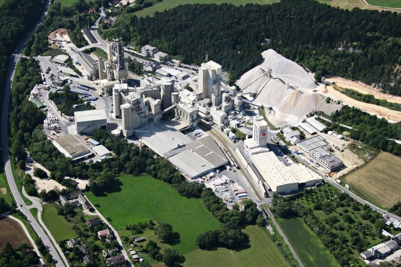
Limestone (from the plant’s own quarry), clay and quartz sand are burnt to cement clinker in a rotary kiln preceded by a five-stage cyclone preheater with cal-ciner. The clinker capacity is 1300 tpd. Pulverized lignite and natural gas are used as fossil fuels, plastics and paper fibre rejects are used as secondary fuels. The thermal substitution rate is more than 75 %. In 2005 an SNCR was installed to reduce NOx to a level of 400 mg/Nm3. Cement grinding takes place in a combined grinding plant (two roller presses and one ball mill).
One of the reasons for odor emissions was the use of clay and paper rejects. In 2001 Wopfinger started pilot testing different technologies, like the injection of liquid odor reduction chemicals, ozone dosing, a fixed bed adsorber, entrained flow absorber and an SCR. These measures to reduce the odor at the stack of the cement kiln were only marginally successful.
In 2009 a two-month test of a pilot scale Regenerative Thermal Oxidizer (RTO) was executed. This achieved good results in reducing the carbon monoxide, total organic carbon and odor emissions. Also successful was the injection of ammonia to the RTO´s combustion chamber after the integrated Selective Non-Catalytic Reduction (SNCR) system. It reduced the NOx emissions significantly.
2 Implementation of the RTO
A precondition to run an RTO is an efficient dust cleaning system (< 10 mg/Nm3). This was the reason the plant replaced their two electrostatic precipitators with a new fabric filter system along with other modifications to the flue gas system. The work progressed as follows:
Autumn/Winter 2010/11: Erection of the fabric filter and adaption flue gas system
Spring 2011: Begin filter operation, dismantle electrostatic precipitators and erection RTO/SNCR
Summer 2011: Begin operation of the new system with RTO/SNCR
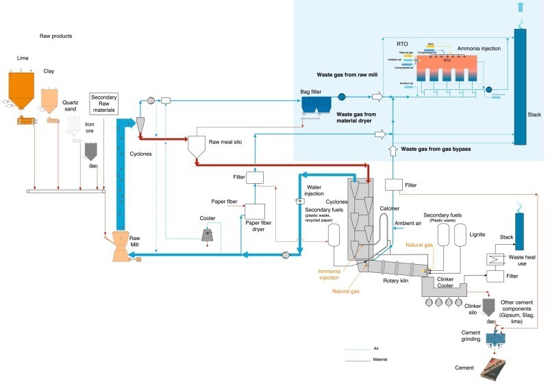
The completed system represents a classic end-of-pipe-solution – where upstream production processes are not affected by the new equipment. With this installation all waste gas streams coming from the kiln can be cleaned. This includes the waste gas from the raw mill, the paper reject driers and the chlorine gas bypass. The process flow of the complete clinker burning process, including the RTO/SNCR is shown in Figure 2.
3 RTO operation
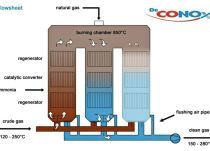
The raw gas is directed through the monolithic ceramic heat exchangers where it is heated close to oxidation temperature. Then it arrives at the combustion chamber where harmful compounds are oxidized without residue. The hot purified gas then passes again through the ceramic heat exchanger beds where it releases its thermal energy (thermal efficiency more than 95 %). The organic compounds and CO contained in the raw inlet gas is often sufficient to run the RTO auto-thermally – not requiring additional fuel. When running autothermally, the main energy user in the system is the fan used to ventilate the RTO and associated ductwork.
Typically, high efficiency RTOs, such as the one at Wopfinger have an odd number, generally three, five or seven identical heat exchanger beds, where waste gas is heated up and cooled down in cycles. The duration of the regeneration cycle is usually between 30 and 60 seconds. To change the direction of gas flow, poppet valves are integrated in the waste and clean gas distribution pathways. By using these valves to switch the waste gas flow between the heat exchangers, the thermal efficiency of the RTO is optimized.
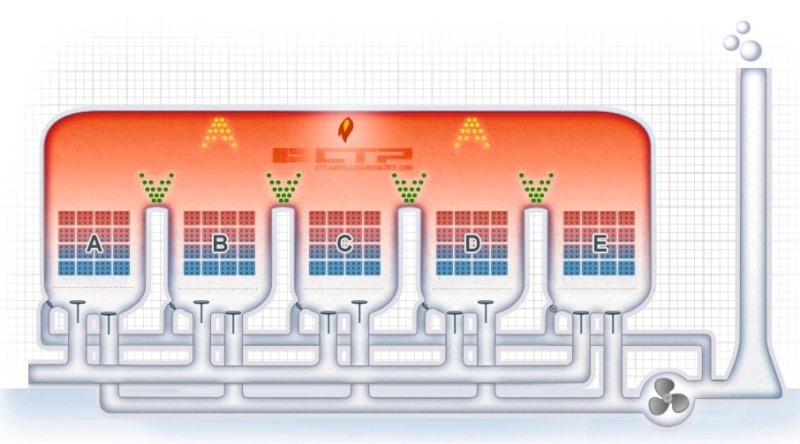
In Wopfinger’s five-bed system, two beds are cooled with raw gas entering the combustion chamber, two beds are heated up with purified gas leaving the combustion chamber, while the odd bed is purged with clean gas or sometimes fresh air, delivered by the purge system. Waste gas flushed from the odd bed is processed in the combustion chamber to avoid emission peaks while switching the gas flow at the end of each regeneration cycle. A diagram of the RTO is shown in Figure 3.
4 RTO design parameters
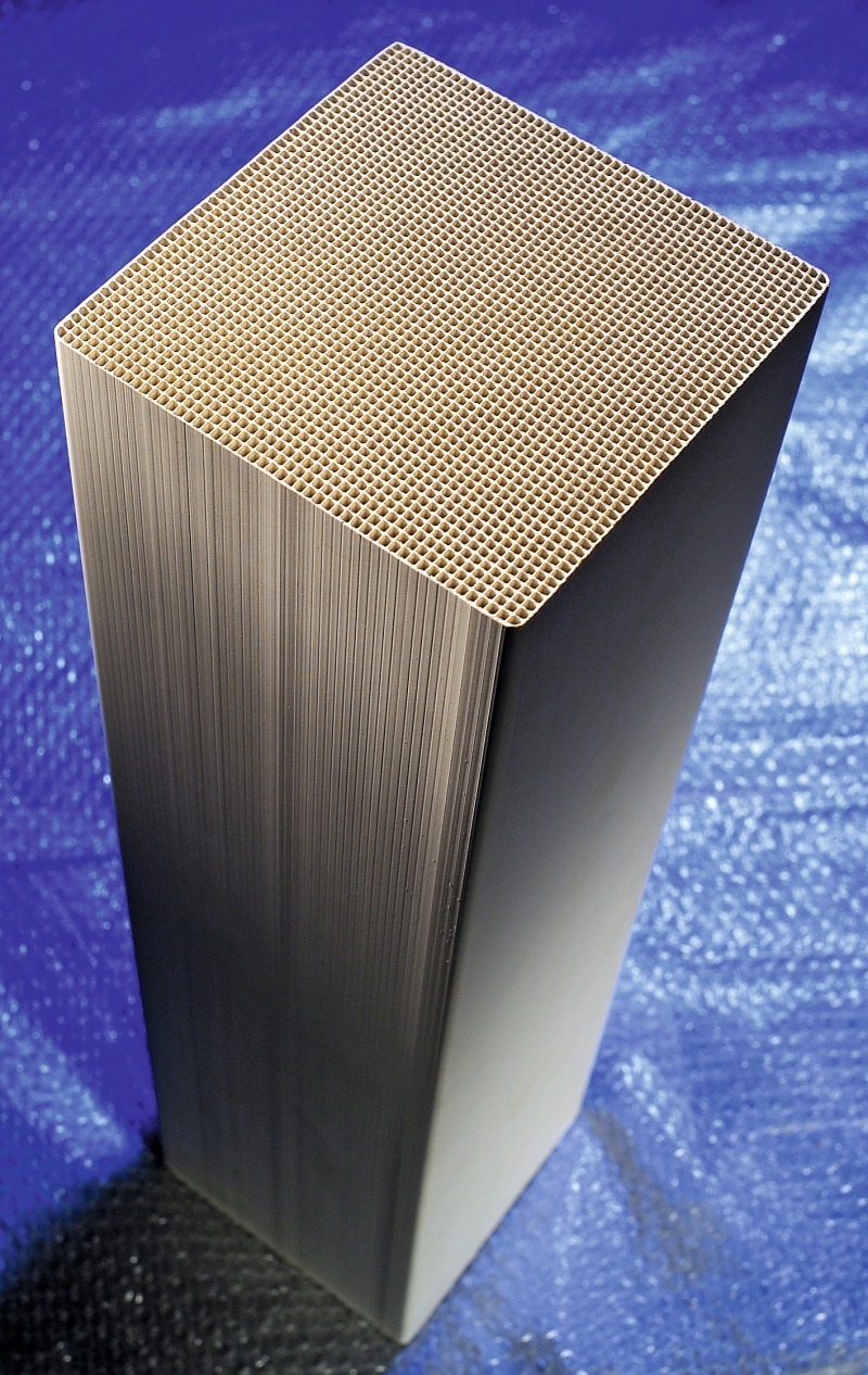
They are arranged in 5 layers with 25 x 40 blocks per layer. The blocks are produced in a ceramic factory in Hermsdorf/Germany owned by CTP and are specifically optimized for thermal stability, resistance to chemical attack and heat transfer characteristics required in the different areas of the heat exchanger. The total heat exchanger surface area is about 145 000 m2. Overall dimensions of the RTO are 26 m long, 10 m wide and 12.5 m high. Because of shortage of space the fan and the clean gas duct are situated underneath the RTO. This results in a total height of 22 m. The total weight of the RTO is approximately 350 tons. Each poppet valve has a diameter of about 1.8 m.
A hot gas bypass was installed to give the operators a means to bypass hot, purified gas around the heat exchangers when necessary. This gives Wopfinger additional flexibility to process gas streams that are highly variable in concentration, as well as to tolerate upsets in the process without overheating.
The Wopfinger RTO was designed to run in autothermal mode at a total raw gas contaminant level of 5000 mg/Nm3 CO, but using the hot bypass system, streams with concentrations up to 20 000 mg/Nm3 CO can be processed without problems.
To reduce NOx emissions the combustion chamber is equipped with 40 two-component nozzles – 8 per heat exchanger bed – which spray an atomized ammonia/water solution into precise locations within the combustion chamber in a carefully controlled manner.
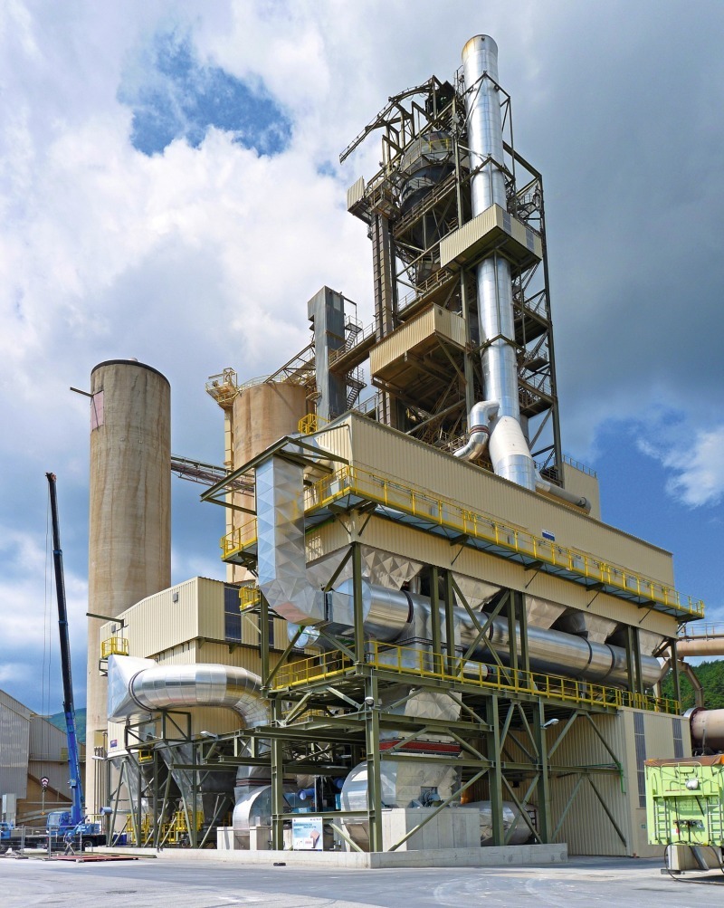
A picture of the RTO with the preheater tower in the background is shown in Figure 5.
5 Operational experience
During normal operation the flue gas from the raw mill and the paper fibre driers are cleaned by the RTO. Because of the possibility of plugging the heat exchangers with dust, all gas streams are equipped with continuous dust detectors. If the dust concentration of any stream exceeds 10 mg/Nm3 the offending gas stream automatically bypasses the RTO until the situation can be corrected.
The stack exhaust temperature has increased from 110 °C to 200 °C. Since the removal of the electrostatic precipitators, there is no further need to water-cool the flue gas leaving the preheater tower. The inlet temperature of the RTO is about 150 °C. Another reason for the hotter stack temperature is the RTO itself. Depending on the raw gas concentration the increase of temperature across the RTO is typically between 40 and 70 °C.
The differential pressure across the RTO is about 35 mbar. Higher pressure may indicate fouling of the ceramics caused by dust or condensation of gaseous compounds like ammonium sulfate. By running a bake-out-cycle the temperature in the cooler areas in the heat exchangers will rise up to 400 °C and the condensation vaporizes in a process similar to a self-cleaning oven. Due to the low NH3 and SO2 concentrations at the Wopfinger plant, it’s necessary to perform bake-out only once or twice each year. This bake-out-cycle can be run during normal operation.
The operation of the integrated RTO/SNCR works together with the existing calciner SNCR. The ammonia dosing into the calciner is controlled by a new NOx monitoring system installed after the preheater tower. The dosing into the RTO/SNCR is controlled by the existing emission monitoring equipment at the stack. By optimizing the dosing and avoiding ammonia slip after the preheater tower a NOx level below 200 mg/Nm3 and a NH3 level below 10 mg/Nm3 at the stack exhaust can be reached (Table 1).
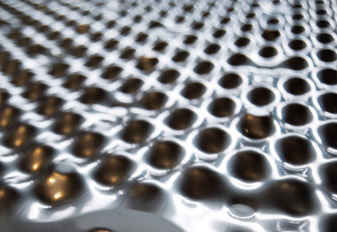
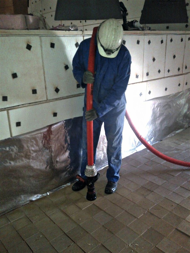
The largest single maintenance cost is cleaning dust deposits from the ceramic blocks. The blocks can be cleaned in place using compressed air or by flushing with water (called a “wash-out”). This wash-out is done by flushing the ceramics from top to bottom, and is more effective than cleaning with compressed air (Figure 6). The complete wash-out procedure can be completed in one week. After ceramic cleaning, Wopfinger’s experience shows that pressure drop across the system is reduced by about 5 mbar.
A. Electricity: The main operating cost is the electricity needed for the fan and the compressed air. Compressed air is used for the operation of the valves and to atomize the natural gas and the re-agent. The electricity consumption is about 8 kWh per ton of clinker produced.
B. Natural Gas: Wopfinger’s experience shows the consumption of natural gas has been reduced from 1.5 Nm3 per ton of clinker to 0.5. This is because of the ability to use other secondary fuels and raw materials containing organic components.
C. Ammonia: To reach 200 mg/Nm3 NOx at the exhaust, up to 5 liters of a 25 % ammonia solution per ton of clinker are needed.
6 Conclusion
The reliability of the system is very high; only one shut-down per year is necessary for maintaining and cleaning the ceramic elements. By having more opportunities to use TOC-containing raw materials and fuels the installation can be operated in an economical way.
It may be possible to transfer these positive operating experiences to other cement plants. However, because of each plant’s specific situation, e.g. use of raw materials and fuels, results may differ from plant to plant. On-site pilot trials at each location may be helpful to determine if the RTO technology (in combination with SNCR or SCR) can be implemented successfully.
Überschrift Bezahlschranke (EN)
tab ZKG KOMBI EN
This is a trial offer for programming testing only. It does not entitle you to a valid subscription and is intended purely for testing purposes. Please do not follow this process.
This is a trial offer for programming testing only. It does not entitle you to a valid subscription and is intended purely for testing purposes. Please do not follow this process.
tab ZKG KOMBI Study test
This is a trial offer for programming testing only. It does not entitle you to a valid subscription and is intended purely for testing purposes. Please do not follow this process.
This is a trial offer for programming testing only. It does not entitle you to a valid subscription and is intended purely for testing purposes. Please do not follow this process.