Heat recovery for energy-efficient
waste gas cleaning


The structure of many industrial and power plants was engineered decades ago and often offers only limited space for the installation of waste gas cleaning systems. Therefore, it is not usually possible to apply in-process methods that clean hot raw gas. The alternatives are waste gas cleaning systems at the cold end. These can be installed further away from the actual process, however, they require in most cases an increase in the waste gas temperature so that, for example, the chemical reaction can take its course in a catalytic converter. To generate the heat with a low energy input, Kelvion supplies the Rekugavo recuperative gas preheater.
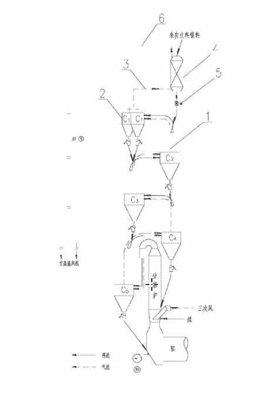
A recuperative preheater is a gas-gas heat exchanger that extracts heat from a stream of hot waste gas and transfers it to the raw gas that is to be cleaned. During ongoing waste gas cleaning, the raw gas can be heated with the heat of the cleaned waste gas almost to the input temperature required for the catalytic converter. Burners or other systems for reheating therefore only have to effect a low temperature increase amounting to just a few Kelvin (Figure 1).
Recuperative gas preheaters are suitable both for denitrification in low-dust DeNOx-systems, on the basis of a SCR catalytic converter...
A recuperative preheater is a gas-gas heat exchanger that extracts heat from a stream of hot waste gas and transfers it to the raw gas that is to be cleaned. During ongoing waste gas cleaning, the raw gas can be heated with the heat of the cleaned waste gas almost to the input temperature required for the catalytic converter. Burners or other systems for reheating therefore only have to effect a low temperature increase amounting to just a few Kelvin (Figure 1).
Recuperative gas preheaters are suitable both for denitrification in low-dust DeNOx-systems, on the basis of a SCR catalytic converter (tail-end systems) and for additional desulphurization in low-dust DeSNOx or waste gas post-combustion systems.
The gas preheater for low-dust DeNOx systems designed by Kelvion was designed to ensure the following features:
smaller plot space and low construction volume
easy transport and installation
high heat recovery (low energy costs)
good temperature distribution based on the countercurrent principle
reliability and low-maintenance operation
durability, in part because of the absence of moving parts
The gas preheaters are suitable for operating pressures up to 400 mbar and nominal volume flows of a few thousand standard cubic metres per hour to over two million Nm³/h. Depending on the application and waste gas cleaning, the temperature of the raw gas after gas preheating in the recuperator is up to above 400 °C (for DeNOx with ammonia).
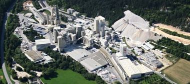
1 Compact design
Depending on the design, over 90 % of the heat contained in the cleaned waste gas can be made usable for the stream of raw gas. The good heat transfer means a lower material input, which results in small dimensions and a lower weight of the entire design. Therefore, in comparison, the Rekuluvo/Rekugavo weigh about half the weight and have half the plot space of a conventional heat exchanger with the same capacity. To keep the footprint of the entire waste gas cleaning system small, Kelvion includes the catalytic converter in the system design and structure. It can be installed above (Figure 2) or below the gas preheater.
The gas preheating stage consists of transportable containers fitted with several heat exchanger modules. For the replacement of the modules, only around two metres depth are needed in front of the container. This is an advantage compared to designs of relatively large connected plate heat exchangers or shell and tube heat exchangers as both are typically several metres long and require correspondingly more working space for removal of the heat exchanger if this has to be replaced.
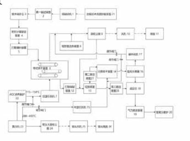
2 Modular design
The size and number of the heat exchanger containers making up the Rekugavo depends on the gas mass flow and the required temperature increase. For transport reasons, the containers reach a maximum height of 4 m, length of 9 m, and width of approximately 2.70 m weighing up to 80 t.
Inside they contain packs of plate heat exchangers each with a depth of around 760 mm. These packs are inserted into the container behind and next to each other (Figure 3). The plate packs are connected to the container at the bottom. On the top a compensator is used to fix them in place. It compensates for the differences in thermal expansion of the container walls and heat exchangers. On the sides of the packs, skid-like elements ensure that the heat exchangers can glide along the container walls with little resistance.
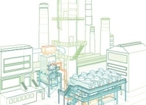
3 Proven plate profiles for better heat transfer
The heat exchanger plate packs consist of a large number of machine-welded heat exchanger plates with a special, proven profile (Figure 4). This profile ensures turbulence in the heat exchanger, which is conducive to heat exchange and, as a side-effect, can counteract the deposition of any dirt particles. With the profiling, an undesirable mechanical tension in the metal plate is avoided. That means the plate edges remain straight and can be effectively machine-welded, which makes them remarkably air-tight (> 99.9 %), Both make the plates rugged and resilient to load changes or mechanical stress.
Within the plate packs, the gas flow is usually based on the countercurrent principle as it allows optimum heat exchange and a high temperature of the raw gas at the outlet. Here the raw gas – presuming the catalytic converter is above the heat exchanger – flows from the bottom to the top and clean gas from top to the bottom through the plates.
4 Plate characteristics adjusted to the application
While the mass flow and the degree of heat recovery and the raw gas target temperature has an influence on the number and height of the containers and the size of the plates used, the material of the plates, their thickness and their spacing depend significantly on the operating temperatures, the substances and dust in the raw gas. As materials, steel (DC04), plain stainless steel, especially corrosion- or heat-resistant alloys or even the high-grade Hastelloy are possible. The plate thickness is generally 0.6 to 1 mm. The plate spacing depends on the permissible pressure drop, the type of dust load and the associated cleaning requirement as well as other criteria. In most applications, it measures 6 mm to 8 mm. The width of the plates is exactly 1060 mm in all Kelvion Rekugavos, the height can measure 938 to 2978 mm.
5 Complete incl. nozzles and hoods
So that the heat exchanger can be optimally integrated in the overall plant, Kelvion generally designs and makes the nozzles and hoods through which the raw gas is sent from the plant to the waste gas cleaning. They are used for the connection with the catalytic converter and through which the pure gas flows in the direction of chimney. The hoods are optimized in terms of flow based on years of experience. The hoods’ design of a Kelvion-Rekugavo is modular: these can be dismantled in segments, so that they can be easily transported by road.
//www.kelvion.com" target="_blank" >www.kelvion.com:www.kelvion.com
Überschrift Bezahlschranke (EN)
tab ZKG KOMBI EN
This is a trial offer for programming testing only. It does not entitle you to a valid subscription and is intended purely for testing purposes. Please do not follow this process.
This is a trial offer for programming testing only. It does not entitle you to a valid subscription and is intended purely for testing purposes. Please do not follow this process.
tab ZKG KOMBI Study test
This is a trial offer for programming testing only. It does not entitle you to a valid subscription and is intended purely for testing purposes. Please do not follow this process.
This is a trial offer for programming testing only. It does not entitle you to a valid subscription and is intended purely for testing purposes. Please do not follow this process.