Optimization of the
thermal substitution rate – Part 1
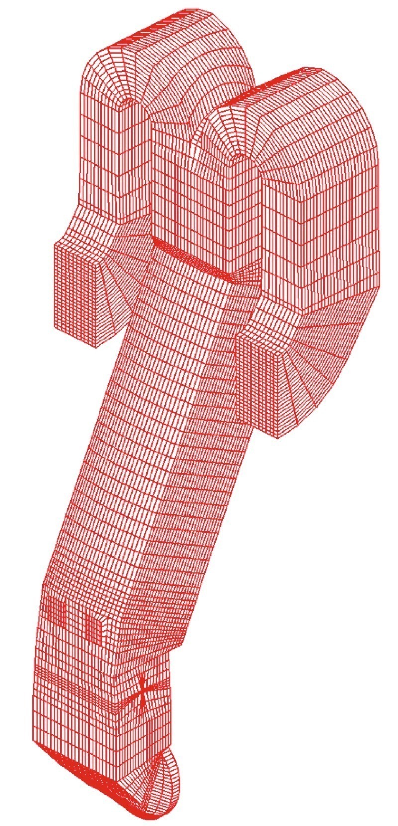
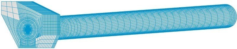
![3 Illustration of air-through precalciner riser duct [dimensions in mm]](https://www.zkg-online.info/imgs/101531654_9d4837b4a2.jpg)
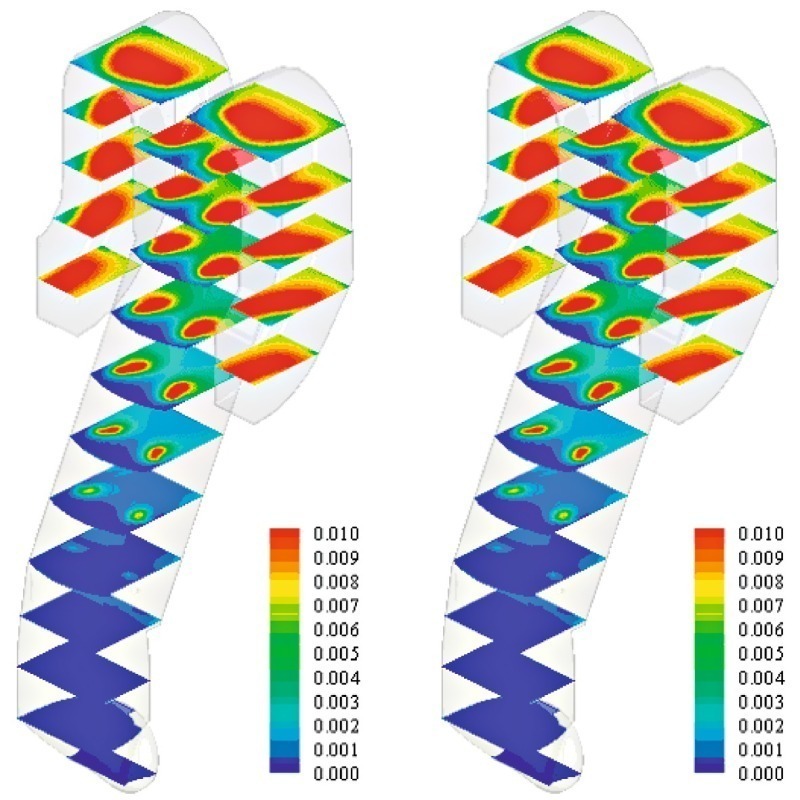
![10 Oxygen concentration [kg/kg] (cut off at 6 % O2)](https://www.zkg-online.info/imgs/101531553_75144a2a0b.jpg)
![11 Temperature distribution inside the precalciner riser duct chamber [in C°]](https://www.zkg-online.info/imgs/101531533_9598fd44d2.jpg)
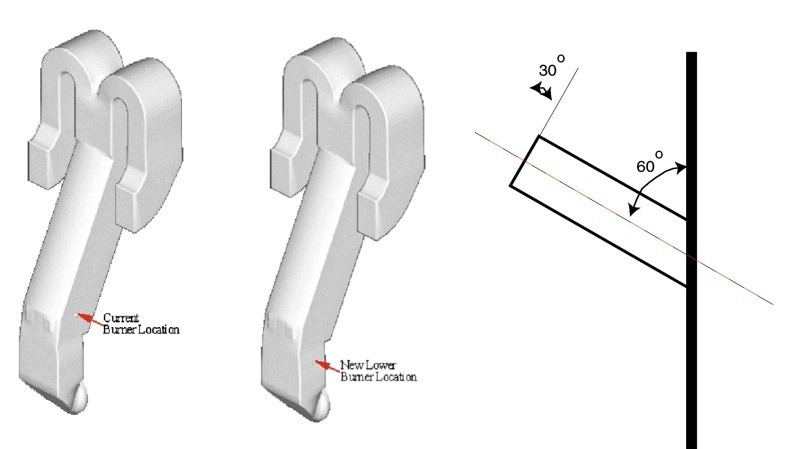
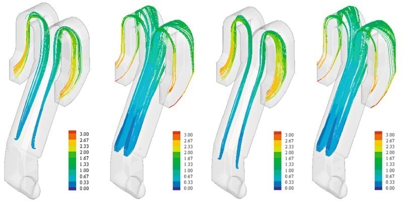
![13 Petcoke particles’ residence time in the riser duct (a = Base case, b = extended riser duct with lower burner location) [in sec.]](https://www.zkg-online.info/imgs/101531570_1c5be104db.jpg)
![15 Kiln hood, kiln burner and kiln layout [dimensions in mm]](https://www.zkg-online.info/imgs/101531544_9d400b1b3f.jpg)
![18 Temperature profile [in °C] (Temperature at oven exit = 1077°C)](https://www.zkg-online.info/imgs/101531597_45ea4bc28f.jpg)
![19 Oxygen concentrations [in mass %] (O2 concentration at oven exit = 5,75%)](https://www.zkg-online.info/imgs/101531658_a2c0531c5f.jpg)
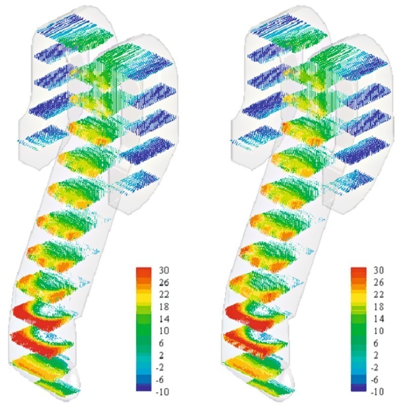
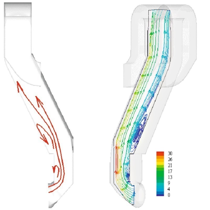
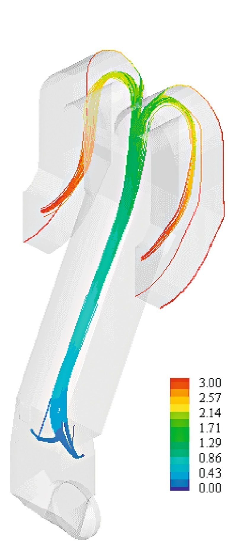
![20 Velocity vector field with magnitude [in m/s]](https://www.zkg-online.info/imgs/101531520_03e0950863.jpg)
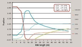
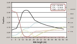
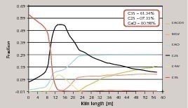
![21 Kiln bed temperature along the kiln length [in °C/m]](https://www.zkg-online.info/imgs/101531617_ff1b7b1980.jpg)
By means of MI-CFD modeling, improvements to AFR thermal substitution rates (TSR) can be easily validated. Two case studies are presented where coal and natural gas were replaced with petcoke and AFR (SRF and BS).
Introduction
Introduction
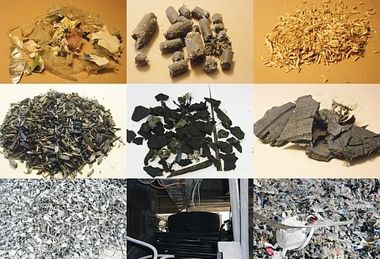
Generally, TSR higher than 20 % to 30 % requires detailed analysis of not only combustion phenomenon of AFRs’ and petcoke but also their impact on emissions, kiln stability and clinker quality. Typically, larger fuel fractions are more difficult to burn fuels, i.e., tyre chips fall down on the kiln bed or into the kiln hot meal feed i.e., petcoke (if injected into a calciner or preheater) and do not combust after getting mixed up with the kiln feed, produce sulphur cycles, as the unburnt carbon reacts with CaSO4 in the after calcination zone at a temperature of approximately 900 °C.
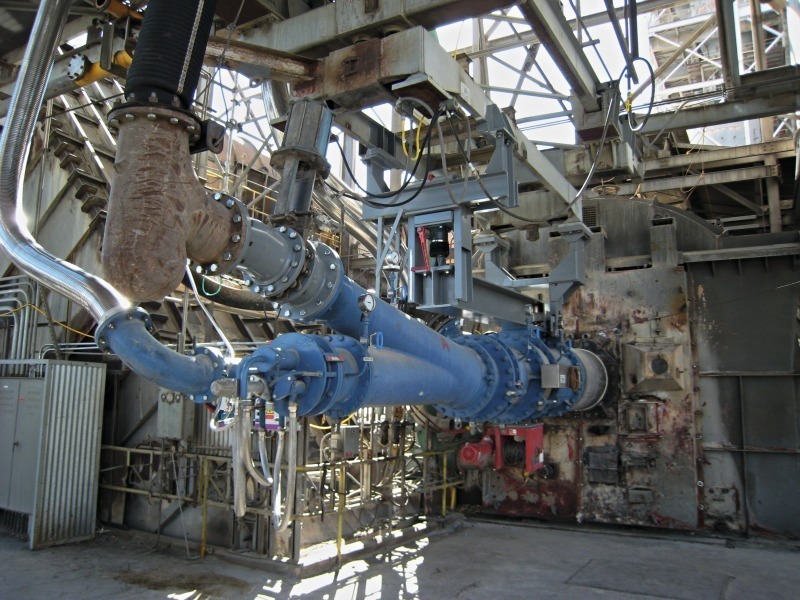
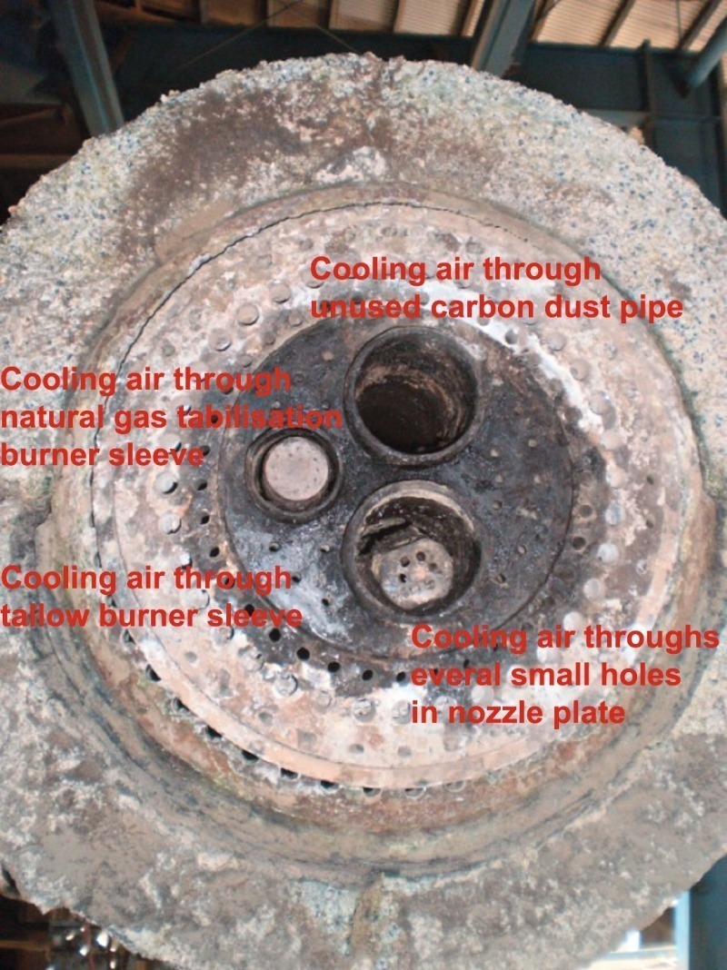
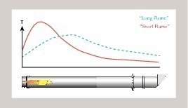
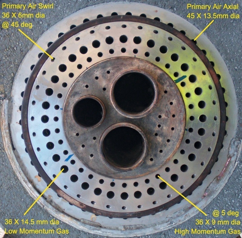
The modern kiln burners (Fig. 1) usually have multi-channel inlets and facilitate higher momentum to thermal load ratios (10–12N/MW) along with provision of co-firing a number of liquid and solid alternative fuels with primary fuels such as coal and petcoke. In principle, a good flame should result but the burner, kiln hood, cooler layout may effect secondary air and tertiary air take off flows, by imparting swirl and causing poor mixing between the secondary air and the burner fuels and thereby, lowering burn-out and increasing kiln CO and increased SO3 cycles/build up.
The fall-out of the unburnt fuel fractions, i.e., from heavier fractions of the ARF, is usually characteristics of the burner momentum and injection strategies of the solid fuels. In particular, the effect of volatile cycles as well as CO and NO emissions need to be brought under control. Provided these conditions are effectively managed, most commercial burners available give good performance, subsequent to some initial adjustments, i.e., burner-kiln alignment, degree of orientation and burner tip location with respect to kiln nose-ring [1, 2].
In comparison to kiln burners, the calciner burners are more flexible in handling fuel variability of the conventional as well as alternative fuels and have several ports available for the injection of fuels, unlike single kiln burners. However, care must be taken to avoid fallout of unburnt fuel fraction into the kiln back-end, which if dropped, would gradually burn, with the little oxygen present in the kiln combustion products. The unburnt fuel fraction, if not fully burnt until the end of the calcination zone within the kiln, would lead to release of SO2/SO3.
In the absence of detailed information on air-fuel mixing and calcination reactions, it is impossible to identify the relative impact of an underperforming burner because of the presence of flame quenching caused by endothermic meal reactions. This is the reason why calciner burners have received little or no attention and are normally just mono-tube burners introducing the fuel with transport air at approximately 30 m/s.
With both preheater/precalciner configurations and inline/separate line layouts, these burners would be subjected to entirely different conditions as compared with kiln burning conditions; i.e.:
Vitiated air conditions (combustion gases from the kiln containing 2–4 % oxygen),
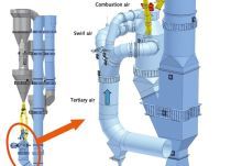
Mixing of high momentum and co-flowing kiln and tertiary air streams (Fig. 2),
NOx reduction potential through creation of “Hot CH-Radical Zone” or “Hot Reburn Zone”,
Build-up problems due to condensation of sulphur and alkali species,
Fallout of heavier chunks of AFR’s initiating blockages and pressure drop issues,
Much shorter calciner residence times as compared with a kiln
Therefore, a well designed/optimised performance of both kiln and calciner burning arrangements would help in increasing higher thermal substitution of AFRs and petcoke as well as ensuring stable kiln operation. In this paper, some of such improvements to customers plants, achieved through application of a novel process knowledge driven, multi fuel, mineral interactive computational fluid dynamics (PKD-MF-MI-CFD) tool are outlined and a few examples for plants are given.
Cement plants embrace alternative fuels, depending on availability, costs, effects on product quality, output and environmental issues. The substitution rates of these fuels depend, to a large extent, on local conditions, as some plants edge closer to the negative fuels costs, i.e., using fuels with gate fees (e.g., hazardous fuels) whereas some plants successfully make use of lower cost alternative fuels, i.e., petcoke, municipal solid waste or its derived fuels, tyres/trye chips. The first two AFR utilisation constraints (AFR availability and costs) are usually plant specific and little can be done to overcome those barriers but the effect of latter three (AFR’s negative impact on clinker quality, production rate and environment) could be minimised, i.e., through fuel handling, preparation, feeding and combustion and process modifications. This paper deals with the improvements to AFR thermal substitution rates (TSR), considering two widely used primary fuels, natural gas and coal, whereas TSR for petcoke and waste derived fuels is considered for both kiln and calciners. Two case studies are presented where coal and natural gas were replaced with petcoke and AFR (SRF and BS).
Case study I
In order to better understand calciner thermo-fluid dynamics features, a detailed MI-CFD modelling campaign was initiated with the emphasis on visualisation of the effect of various calciner improvement designs. This could be affected to increase the plant’s lost output, while focusing not only on the clients design improvement proposals but also contributing Cinar’s own expertise for the identification of the most suitable solution for calciner’s improved petcoke combustion performance.
The impact of relocation of the petcoke burners below the stage-III meal injection position,
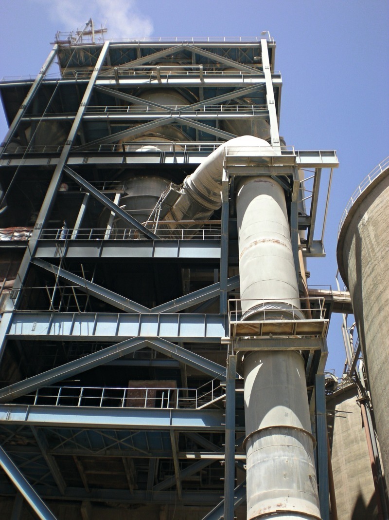
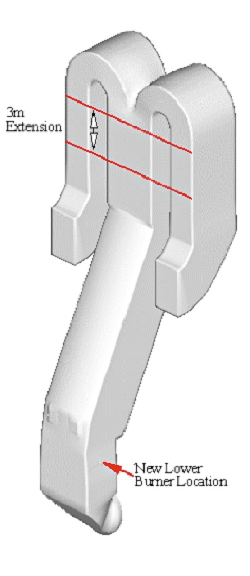
The influence of extending the precalciner riser duct for enhancing the residence of fuel and hot-meal particles,
The benefits of burner enhancement through injection of axial air into the burner pipe.
Calciner geometry and its current operating conditions
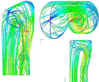
Figure 6 shows the velocity vectors and the upward component of velocity for the base case as compared with the lower burner (case I.). Initially, there is a reverse flow region at the bottom of the riser duct, (lower section) due to upward diversion of the kiln gases once entering into the riser duct. This can clearly be seen where the blue colour contours (-10 m/s) indicate regions of flow re-circulation near the rise duct wall (closer to the kiln).
There is also a second region of reverse flow at the beginning of the middle section (Fig. 7). The higher velocity region persists within most of the middle section, however, both the upward velocity magnitude and the size of the region are smaller as compared with the lower section. There is little indication of any re-circulation region in the upper section of the riser duct and the flow becomes relatively uniform before entering into the two arms.
For a lower volatile solid fuel, i.e., petcoke, it is important that particles spend more time at higher temperature and higher oxygen regions in the wake of their path to calciner exit. The overall particle burnout, of course, also depends on the fineness of the petcoke along with the particles’ residence time inside the chamber.
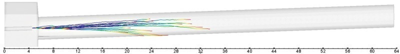
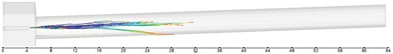
The injected petcoke particles (Fig. 8) are observed to penetrate slightly more into the upward directed flow of kiln gases in the base case as compared with the lower injection case (case I). This is due to the fact that the base case petcoke particles are injected into the area where lower upward velocity region persists, as compared with the new lower burner position. Hot meal particles (Fig. 8) showed similar trajectories and penetration covering only one region of the chamber before being dispersed within the chamber in the upper section. There is some increase in the petcoke residence time between the base case and case I, however, it is not equivalent to the distance by which the burner has been lowered. This is due to the fact that velocities are higher in the lower section of the riser duct as compared with the base case burner location duct which has higher cross sectional area.
Figure 9 shows the mixing of the released carbon dioxides resulted from the char carbon combustion, which slows the slower char burnout due to its delayed ignition of lower volatile content particles. The plot clearly shows ignition delay effect between the injection point and the position at which the char started burning. It is, however, important to note that the contours, shown in Figure 9, have been cut at a very low level (0.01) to amplify their effects. Lowering the injection location somewhat reduces the ignition delay of the petcoke particles. For petcoke, it is important to have finer ground particles and to allow for slighly higher oxygen concentrations within the kiln gas (3–4 %) as compared with coal, or alternatively preheat tertiary air (21 % O2) to lower the ignition delay of the petcoke particles.
The availability of oxygen in the region where particles travel is shown in Figure 10. The depletion of oxygen takes place in the region where petcoke particles travel and slowly react with oxygen at the particles open pores, created by evolved volatiles during the devolatilisation phase. The petcoke particles’ trajectories, in the absence of any cross-duct mixing mechanisms, induce flow stratification where unconsumed O2 is not diffused into the reaction zone (Fig. 10).
Pre-calciner riser duct extensions
Figure 13 shows that lowering the burner position had enabled petcoke to gain a little extra residence time within the chamber however, the high momentum kiln flow in the lower section had minimised the benefit by accelerating the petcoke particles and also by pushing them closer to the walls. The low volatile matter content of petcoke, as expected, is the reason for the slow ignition shown here. The combined effect of lowering the petcoke burners and extending the height of the precalciner by 3 m (Fig. 13) had only a marginal effect on char burnout and calcination levels as shifting the burners also comes immediately under the influence of calciner meal paricles which “quench” the flame and hence some benefit is gained later on with slight increase in the petcoke burn-out, of the order of 4 and 5 % in the petcoke burnout and hot meal calcinations level, respectively.
Conclusions
The proposed upgrade was thoroughly assessed through MI-CFD simulations. In the light of previous experience at other plants, it was decided to improve the performance of the petcoke burner by introducing a higher momentum, which resulted in increasing the burning rate of petcoke at almost 11 % and also raised the calcination level by 6 %. An increase, that was achieved mainly through particle penetration into the riser duct flow and improved mixing with the region of high oxygen as can be seen from Figure 14 where petcoke particles are seen to be dispersing more into riser duct flow.
The plant subsequently abandoned the extension of the riser duct by 3 m and implemented the higher momentum burner option, which was more cost effective than extending the volume of the calciner. In addition, after presentation of complete MI-CFD analysis, the incorporation of the tertiary air duct was also adjourned for a future plant upgrade and a more convenient and cost effective burner modification, installation of tailored high momentum burner, was accomplished by spending less than 50 000 €. After operating about one year, the plant reported the following benefits: 8 % increase in the calcination levels; carbon in the hot meal reduced from 0.3 to 0.1; less deposit build-up and ring formation; fuel substitution in the precalciner increased by 5 %; clinker production increased by 4 %.
Überschrift Bezahlschranke (EN)
tab ZKG KOMBI EN
This is a trial offer for programming testing only. It does not entitle you to a valid subscription and is intended purely for testing purposes. Please do not follow this process.
This is a trial offer for programming testing only. It does not entitle you to a valid subscription and is intended purely for testing purposes. Please do not follow this process.
tab ZKG KOMBI Study test
This is a trial offer for programming testing only. It does not entitle you to a valid subscription and is intended purely for testing purposes. Please do not follow this process.
This is a trial offer for programming testing only. It does not entitle you to a valid subscription and is intended purely for testing purposes. Please do not follow this process.