The tubular weigher WeighTUBE® – the innovative bulk material dosing system

1 Alternative fuels for the cement industry
Particularly in the cement industry, recent years have seen the replacement of conventional fossil fuels with alternative fuels. Aside from biomass, sewage sludge, automobile tyres, animal meal and municipal wastes, the preferred substitute fuels are industrial wastes with a high calorific value. These powdery, granulated, pelletized fibrous and flocculent secondary fuels derived from quality-controlled industrial wastes are generally known as fluff (gas-entrainable fine materials). Fluff is almost exclusively used as a source of energy for the...
1 Alternative fuels for the cement industry
Particularly in the cement industry, recent years have seen the replacement of conventional fossil fuels with alternative fuels. Aside from biomass, sewage sludge, automobile tyres, animal meal and municipal wastes, the preferred substitute fuels are industrial wastes with a high calorific value. These powdery, granulated, pelletized fibrous and flocculent secondary fuels derived from quality-controlled industrial wastes are generally known as fluff (gas-entrainable fine materials). Fluff is almost exclusively used as a source of energy for the cement burning process. As a rule, gravimetric dosing devices are used. High demands are imposed on the design of industrially applicable gravimetric dosing systems for secondary fuel, as such fuels have difficult physical bulk material properties, such as
a very low bulk density, resulting in a very high volumetric flow, and which is also subject to short-term fluctuations,
a high dust content,
a strongly fluctuating gross calorific value,
a tendency to form large agglomerations due to the stable mechanical bonding of secondary fuel constituents, leading to a distinct risk of bridging,
a fluctuating moisture content
in addition to problematic flow properties. On top of this, the plant owner also imposes requirements arising from the increasing refinement and thus complication of the burning process, the environmental protection regulations and the possible integration into existing process control and information systems. Industrially applicable dosing systems must have the following characteristics: high accuracy, large control range, short response times, good reproducibility, great reliability and a high level of automation. In accordance with the current state of the art, gravimetric dosing systems are equipped to continuously weigh the material flows and have a higher-level control for regulating the mass flow rate of the bulk material according to a defined setpoint value. Further criteria for a gravimetric dosing system for secondary fuels are:
insensitivity to harmful constituents,
high short-term and long-term precision,
possession of a system calibration facility, best performed automatically during operation,
comprehensive system function monitoring,
high operational reliability,
the same dosing constancy as that achieved with conventional fuels.
Secondary fuels generally have a high dust content, which represents an extraordinarily high explosion hazard. Due to this fact, gravimetric dosing systems for secondary fuels have to be of closed or even in individual cases pressure shock resistant design. Di Matteo has already performed comprehensive tests in which numerous basic criteria were established. These permit a process-relevant characterization of secondary fuels and also define the relevant prerequisites and requirements for a gravimetric dosing system [1-3].
Due to the fact that even small fluctuations in the secondary fuel supply to the rotary kiln of the cement burning process have a direct effect on the kiln atmosphere (O2 and CO content of the kiln gas), strict demands have to be placed on the short-term dosing constancy. The secondary fuel is often pneumatically conveyed to the kiln directly after the dosing. This makes it impossible to compensate short-term fluctuations in the mass flow by buffer storage or recirculation, so that the fluctuations directly affect the gas composition of the kiln atmosphere. This phenomenon occurs especially often when feeding is performed by weighbelt feeders. When clumps of material break off at the discharge end of weighbelt feeders, severe short-term fluctuations in the flow of material are caused. As a consequence, the chemical composition of the kiln atmosphere also undergoes severe fluctuations (O2 and CO peaks).
Systems for the use of secondary fuels as a substitution for conventional fuels generally have to be designed for retrofitting into already existing cement production plants. This generates a compulsion to minimize the space requirement of the dosing system. In addition to this, there is a current trend towards uncompromising minimization of the required capital cost of the system.
2 Design and principle of functioning
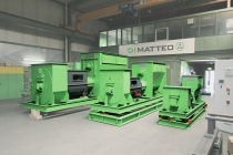
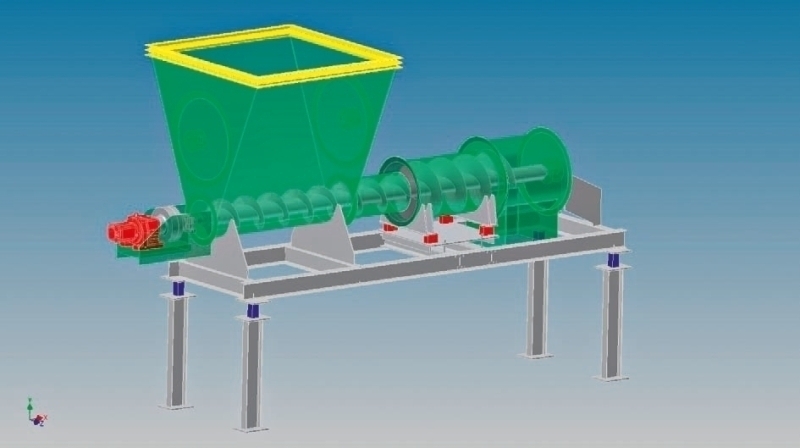
Under the premise of the above requirement specifications, a tubular weigher as an innovative and alternative dosing system, primarily for the problematic secondary fuels and polyethylene granulate material was developed (Fig. 1). Subsequently, it is planned to test the tubular weigher for industrial use with other, particularly conventional bulk materials, such as cement, raw meal, clinker etc.
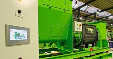
The tubular weigher, whose functional principle is protected by industrial property rights, mainly consists of the following component parts (Fig. 2):
1. Feed hopper: The bulk material feed hopper is the dosing device. The hopper geometry is suited to the properties of the bulk material and is, if necessary, equipped with an agitator. By means of extensive tests, Di Matteo was able to develop the design of the hopper to prevent impermissible compaction of compressible bulk material, such as fluff or other generally used secondary fuels. This ensures optimum conveyance to the downstream process. To avoid stressed connections between the feed hopper and the preceding machines or silos, an expansion joint (shown in yellow in Fig. 2) is installed at the hopper inlet.
2. Dosing section: The dosing section in the form of a screw conveyor casing is located between the feed hopper and the measuring section.
3. Measuring section: The measuring section, the actual tubular weigher, is located between the feed hopper and the outlet head of the tubular weigher. This is mounted on 4 load cells (shown in red in Fig. 2), which record the total weight of the measuring section. The cross-section of the measuring section is greater than that of the dosing section. As a result of the tests performed, the cross-section of the measuring section was specially designed to prevent tramp material from jamming between the measuring section and the screw conveyor shaft. In order to avoid stressed connection to any other parts, the measuring section is decoupled from the dosing section and the subsequent outlet housing by means of expansion joints. The great advantage of the measuring section, the actual WeighTUBE®, is its relatively low dead weight in comparison with the weight of the bulk material inside the WeighTUBE®. This excellent ratio is the key to the unique high precision of the weighing.
4. Outlet housing: Through the outlet housing the dosed bulk material leaves the measuring section and is discharged into the downstream machines. The outlet housing is decoupled from the downstream machines, for example pneumatic conveyors, by means of an expansion joint.
5. Screw shaft with drive: The screw shaft with drive, is – looking in the material flow direction – mounted at the front in the vertical end wall of the feed hopper and at the rear in the vertical end wall of the outlet housing. This screw shaft conveys the bulk material out of the feed hopper, via the dosing section to the measuring section, where it is weighed, and subsequently discharged into the outlet housing. While the diameter of the screw is identical in the feed hopper and the dosing section, it is increased in the measuring section.
6. Machine frame with load cells: The tubular weigher, consisting of the feed hopper, the dosing section, the measuring section, the outlet housing and the screw shaft is mounted on the machine frame. It is weighed statically by means of the weigh cells (shown in blue in Fig. 2). This external weighing controls the feeding of bulk material to the feed hopper and maintains a constant filling level in the hopper. Furthermore, it is used for calibration of the system.
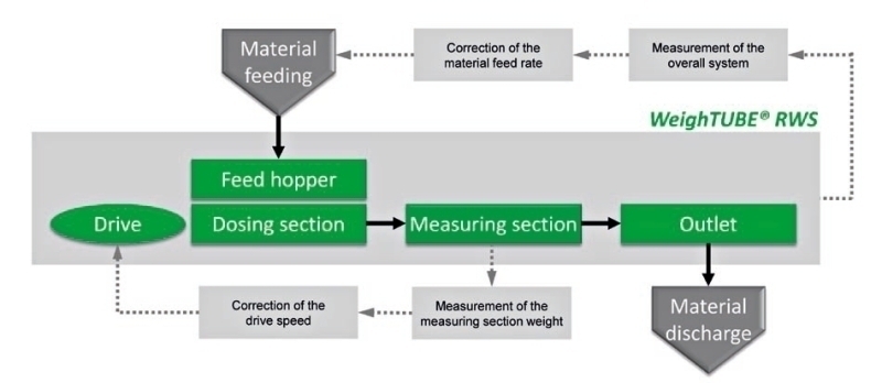
The functional principle of the tubular weigher is schematically represented in Figure 3. The bulk material is fed to the feed hopper and withdrawn from this at a controlled flow rate by the screw shaft via the dosing section. The drive of the screw shaft is equipped with a frequency converter to enable variation of the drive speed.
The material subsequently passes into the measuring section, where it is continuously weighed. The calculated net weight of the measuring section is used for correction of the drive speed of the screw shaft. Due to the relatively short residence time of the bulk material in the dosing section and the measuring section, this correction takes place in accordance with the geometric and constructional conditions at time intervals of just a few seconds. The prerequisite for precise drive speed control is a linear relationship between the screw shaft speed and the screw flight pitch.
However, tests performed by the VDI on screw weighfeeders [4] revealed that the conveying speed of the material in the screw conveyor is not an exact result of the screw flight pitch and the screw shaft speed. This finding by the VDI explains the relatively large measurement and dosing error that often occurs during industrial application of conventional screw weighfeeders. In the course of development of this tubular weigher by Di Matteo of Beckum, design features and operating conditions were developed that enable a linear relationship between the above-mentioned parameters and thus allow a dosing error < 1.0 % to be achieved.
To obtain the maximum possible material filling level in the feed hopper, the weight of the overall system is determined and the material feeding is automatically controlled (Fig. 3). To illustrate the functionality of the tubular weigher, Figure 4 graphically represents a measured actual throughput (MIST) of fluff as a function of the measuring time (t) at a target throughput (MSOLL) of 2500 kg/h. Throughout the test period, the actual throughput rates corresponding to the integral measuring time were recorded at intervals of 2 secs. Table 1 shows the key data that were obtained for the test period. The regression analysis of all measuring points in Figure 4 resulted in the following linear relationship:
MIST = MIST (t) = -0.00017* t + 2476.4
The extraordinarily low rise in the regression lines indicates that no significant zero point displacement could be observed in the tubular weigher control during the examined period of time.
Häfner et al. [6] ascertained that rotary weighfeeders and conveyor scales are subject to a long-term zero point displacement. This phenomenon was also found in long-term tests of the tubular weigher, but to a considerably smaller extent. As a consequence, it is necessary to check the mass flow rate using the so-called check hopper process after a lengthy uninterrupted period of tubular weigher operation and to recalibrate the tubular weigher if required. This checking procedure takes place automatically after a pre-determined operating period that depends on the respective operating conditions, and is carried out without interrupting the system operation. For this purpose, the feed hopper is filled to maximum level, the material feeding is stopped and then the time required for a decrease in overall system weight to a specific minimum value is measured, like in a differential dosing weigher. Subsequently, the tubular weigher is immediately corrected and the material feeding to the feed hopper (1) is restarted.
3 Examples for installed tubular weigher
systems – case studies
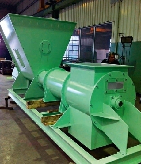
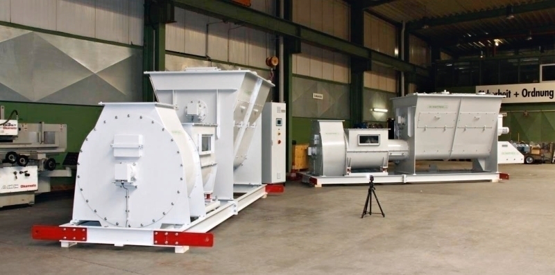
3.1 Trial plant at the testing facility
The process technological principle of the tubular weigher was comprehensively tested at the Di Matteo testing facility in Beckum (Fig. 5). During this phase, the control software of the tubular weigher was also developed. This can be employed on every adequately dimensioned PLC (e.g. Siemens S7).
The test materials used were polyethylene granulate material (throughput up to 4.0 t/h) and different size fractions of fluff-type secondary fuels (throughput up to 5.0 t/h). In addition, dried sewage sludges, biomass and pelletized secondary fuels were successfully tested.
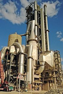
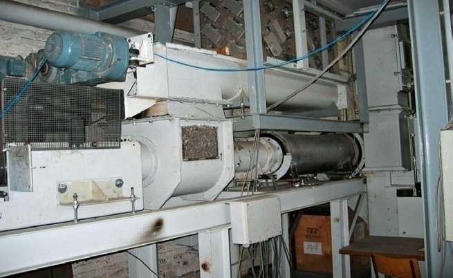
3.2 Tubular weigher for 8.0 t/h in a cement plant
Industrial trials were performed at a German cement works using a tubular weigher for throughput rates of up to 8.0 t/h (Fig. 6). Originally, the secondary fuel was directly dosed by conveyor scale into the burner of the cement rotary kiln. However, O2 and CO peaks occurred in the atmosphere of the rotary kiln due to the already-described phenomenon of material breaking off in clumps at the discharge end of the weighbelt feeders. Thanks to installation of the WeighTUBE® RWS, these peaks and thus the chemical composition of the kiln atmosphere were significantly smoothed. By means of tandem configuration of a conveyor scale and a tubular weigher it was also possible to compare the performance of the two dosing systems.
3.3 Dosing system for 15 t/h in a cement plant
Installation of two dosing systems with a throughput of 15 tph each (Fig. 7) in an existing industrial system for fluff at an English cement works. This system consists of 2 WeighTUBE® RWS tubular weighers in parallel operation. These two tubular weighers have already been in continuous industrial operation for a lengthy period of time to the satisfaction of the plant owner.
4 Prospects
The WeighTUBE® RWS tubular weigher was tested by Di Matteo of Beckum/Germany in the company‘s testing facility as a new and innovative gravimetric dosing system for bulk materials and was developed to technological maturity for industrial use. This statement relates both to the machine technology concept and to the development of the tubular weigher control system program.
The principal advantages of the tubular weigher are:
Low space requirement, ensuring retrofitting of the system into existing plants
Comparatively low capital cost
Robust execution enabling use under difficult production conditions
High dosing precision of < + 1.0 % related to the nominal throughput
Enclosed design, preventing dust emission and explosion hazard
Good integration, including incorporation into existing control and information systems of the entire plant
Automatic recalibration facility (setting of zero point) without interrupting the continuous production operation
Large throughput rate control range
The industrial scale tubular weighers already installed are operating successfully with throughput rates of up to 15 tph. Di Matteo of Beckum has thoroughly tested the WeighTUBE® RWS tubular weigher for weighing and dosing of secondary fuels, particularly with regard to fluff and the model material PE granulate. In the future, its area of application is to be extended to conventional bulk materials such as raw meal, filter dust, clinker, cement etc.. Upon request, potential clients can attend demonstrations using their desired bulk materials at the company‘s testing facility.
Überschrift Bezahlschranke (EN)
tab ZKG KOMBI EN
This is a trial offer for programming testing only. It does not entitle you to a valid subscription and is intended purely for testing purposes. Please do not follow this process.
This is a trial offer for programming testing only. It does not entitle you to a valid subscription and is intended purely for testing purposes. Please do not follow this process.
tab ZKG KOMBI Study test
This is a trial offer for programming testing only. It does not entitle you to a valid subscription and is intended purely for testing purposes. Please do not follow this process.
This is a trial offer for programming testing only. It does not entitle you to a valid subscription and is intended purely for testing purposes. Please do not follow this process.