Proposal for a new kiln process for burning of lump lime
 Thomas Schwertmann
 Thomas Schwertmann
 Thomas Schwertmann
 Thomas Schwertmann
 Metso Minerals
 Thomas Schwertmann
 Thomas Schwertmann
 Thomas Schwertmann
 Thomas Schwertmann
The proposal described below for a lime kiln is based on an idea which is more than 20 years old: firstly, utilisation of the calcining potential of elevated-temperature lime-cooling air, in order then to use the oxygen content of this lime-cooling air (enriched with a small amount of CO2) for burning. For this purpose, it would be necessary to develop a kiln concept in which the hot lime-cooling air is brought into contact with limestone adjusted to the starting temperature for calcining (approx. 820 to 830° C). In the PFR kiln, for example, the lime-cooling air, which should be set at a low flow, is heated almost to the lime temperature at the outlet from the calcining zone. In the PFR kiln, however, this lime-cooling air is only drawn through the waste-gas shaft without being used as combustion air. This idea originates from a period in which the author was intensively involved with the lime-burning process. A diagram of such a kiln process was quickly drawn (Figure 1). Its translation into an implementation-capable kiln concept began to appear ever more difficult as knowledge of lime kilns increased, however. Calculations of energy flows produced the result that a better specific thermal-energy consumption than when using a state-of-the-art PFR kiln is not possible. The basic idea was, for this reason, not pursued further. The topic of “CO2-neutrality” has moved to the foreground in the lime industry, too, for some time now. Even the old engineers‘ adage that “electricity is there for light and power” appears no longer to be true, since there have also been proposals for electrical heating of lime kilns. This then changes the perspective on concepts which, even only a few years ago, appeared of little rationality, and even indirect heating of the burning charge has, for example, been suggested. The goal is to obtain the CO2 that inevitably results from the calcining of the CaCO3 unmixed with combustion waste gases. This pure CO2 would then be used for other processes or, possibly, liquefied and stored underground. Important in this context appears the concept of a so-called oxyfuel kiln based on combustion using pure oxygen [1]. Here, again, the objective is a highly concentrated CO2 kiln waste-gas. Against this new background, the old idea was again taken up, but under the stringent requirement of a “continuous process”.
The current state-of-the-art
Benchmark for any proposed new lime-burning process is the PFR kiln. This type of kiln achieves the lowest possible specific thermal-energy consumption. A whole series of significant improvements to this kiln type have taken place in recent years. Achievable specific thermal-energy consumption depends in every case on the chemistry of the limestone charged and the residual CO2 content of the lime product obtained. The data shown in Table 1 are used in this work.
A state-of-the-art PFR kiln can achieve for these analytical data a specific thermal-energy requirement of...
The current state-of-the-art
Benchmark for any proposed new lime-burning process is the PFR kiln. This type of kiln achieves the lowest possible specific thermal-energy consumption. A whole series of significant improvements to this kiln type have taken place in recent years. Achievable specific thermal-energy consumption depends in every case on the chemistry of the limestone charged and the residual CO2 content of the lime product obtained. The data shown in Table 1 are used in this work.
A state-of-the-art PFR kiln can achieve for these analytical data a specific thermal-energy requirement of ≤3.60 GJ/t lime. The PFR kiln has some disadvantages with regard to the current CO2 discussion. Its operation is, on the one hand, non-continuous, it takes the form of a twin-shaft kiln and it is briefly switched off around 120 times each day for the purpose of shaft changeover. During shaft changeover, the flow of waste-gas falls to zero. Peaks can occur in certain subsidiary constituents of the waste-gas. This fact is problematical for any downstream facilities intended to remove the CO2 from the kiln waste-gas.
In addition, the CO2 concentration in the kiln waste-gas is rather low (approx. 26vol%, dry gas) when operating with pulverised lignite as a fuel, heat demand 3.6 GJ/t, lime-cooling air factor 0.70 Nm³/kg lime and λ = 1.15, for example. This is due to the fact that the entire lime-cooling air is drawn through the waste-gas shaft, and the O2 content of the waste-gas is therefore around 8%vol. and specific waste-gas volume, at approx. 2.4 Nm³/kg lime (waste-gas moist) rather high.
Schematic diagram of the new kiln process
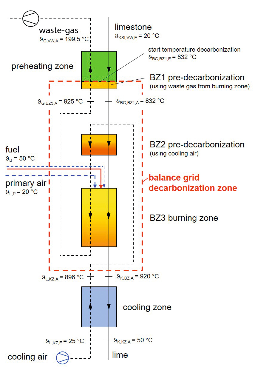
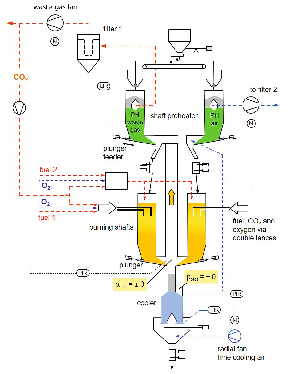
The new kiln process permits genuine “continuous operation”. A version of this kiln process in accordance with Figure 1 is shown in Figure 2. The kiln is made up of three separate pieces of equipment, similarly to those of a rotary kiln. The lime-cooling air is routed into the co-current-flow zone of the kiln and there meets the highly preheated limestone arriving from the preheater shaft. Calcining takes place in Calcining Zone 2 (BZ2) in accordance with equilibrium. The equilibrium function shown below applies to calcite calcining:
⇥(1)
in which Tf = Temperature on the reaction front in degrees Kelvin. This equation supplies for, for example, Jf = 900 °C a CO2 equilibrium pressure of pCO2,eq = 1060 mbar. Calcining continues in BZ2 until the increase in CO2 concentration in the lime-cooling air reaches a limit. Thermal-energy for partial calcining originates from cooling of the lime-cooling air and the limestone to be burned.
In the main calcining zone, BZ3, the fuel is fed, as in the PFR kiln, via lances, which are suspended in the limestone bed. These lances must be so-called double-lances, as the marginally selected lime cooling air is not sufficient as combustion air; in other words, the remaining combustion air required must be fed via the double lances as primary air.
The waste-gas from Calcining Zone BZ3 is routed via refractory-lined pipes to the shaft preheater.
This schematic diagram requires airlocks for the feed material at the outlet from the preheater zone and at the outlet from the calcining zone. Various designs already tried and tested on other kiln types can be selected for lime discharge from the cooling zone.
Heat consumption
The heat consumption of the kiln can be calculated comparatively easily. From a thermodynamic viewpoint, this is a continuous counterflow kiln, because counterflow between the limestone and the hot gas exists at the boundary between the preheating zone and the calcining zone. The individual processes that take place in the calcining zone are of no significance for balancing, the decisive factor is the overall balance of the calcining zone (see [2] for calculation).
A number of important parameters must firstly be defined to permit a specimen calculation. Since co-current flow, as in the PFR kiln, prevails in the main calcining zone BZ3, the kiln supplies soft-burned lime. As in the PFR kiln and the annular shaft kiln (ASK), the temperatures of the hot gas and the lime are practically identical at the outlet from the calcining zone, the lime-cooling air almost reaching lime temperature. The temperature of the crossover gas of a PFR kiln can be used for quality control, since it constitutes a measure of lime temperature at the outlet from the calcining zone and therefore of lime quality, expressed in residual CO2. Similarly as in the ASK, the temperature of the recirculating gas, the mixture consisting of lime-cooling air and co-current-flow gas, can be used for quality control purposes. In the ASK, the temperature of the lime-cooling air at the outlet from the cooling zone is practically identical to lime temperature, since the lime-cooling air is usually run very short. Recirculating-gas temperature is typically between 890 and 930 °C, depending on the limestone charged [3].
It is assumed here that lime temperature at the outlet of the calcining zone is 920 °C. The waste-gas temperature at the outlet of the calcining zone is selected slightly higher (925 °C). There results a lime-cooling air temperature at the outlet from the cooling zone of 896 °C, assuming a lime-cooling air factor of 0.636 Nm³/kg lime and a lime exit temperature of 50 °C.
The flow of coal-conveying air, which is a part-flow of the primary air, should be selected to accord with the necessities of pneumatic conveying, but in all cases, as low as possible. The flow of primary air routed via the double lances is used to adjust the air excess factor for combustion.
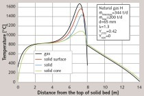
Table 2 shows a compilation of the most important data for process calculation for a kiln with a daily output of 400 t/d. The initial calcining temperature of JBG,BZ,E = 832 °C is the temperature of the limestone at the boundary between the burning zone and the preheating zone. As indicated by the equilibrium equation (Equation 1), calcining just starts to occur at this temperature. Iteration is necessary, since the CO2 concentration of the waste-gas from the calcining zone (here, from BZ1) is the result of the process calculation in the first step. The CO2 concentration of the moist waste-gas at the outlet from the calcining zone becomes 37.1%vol. There, CO2 partial pressure is 371 mbar at a total pressure of approx. 1000 mbar. Figure 3 shows the plots of temperature in qualitative terms.
Kiln operation
Overall, the kiln runs on a suction-pressure-mode of operation. The lime-cooling air is pressurised into the cooling zone by means of a radial fan. The flow of cooling air is regulated on the basis of the target extraction temperature of the lime. The speed of the waste-gas fan is controlled in such a way that a slight underpressure prevails at the extraction point from the burning shaft. The plot of static pressure in the kiln system shown schematically in Figure 4 thus follows. The waste-gas fan thus needs to balance out the pressure loss of the shaft preheater (and the downstream filters). The cooling-air blower is required to overcome the resistance of the cooling zone and the burning shaft. In terms of consumption of electrical energy, this is an advantage, since the work of compression takes place primarily on cold air.
The gas temperature at the outlet from the burning shaft (from BZ3) provides a good indication of lime quality. This temperature – assumed at 925 °C for the specimen calculation – can be used for quality control or, in other words, for adjustment of fuel flow. As in the case of the ASK, gravimetric metering of fuel for this reason appears not to be necessary.
The pressure loss from the kiln system is significantly lower than that of the PFR kiln. Flow takes place through each zone only once. In the PFR kiln, on the other hand, after flowing through the burning shaft, the entire quantity of waste-gas from the burning shaft and the total lime-cooling air flows through the waste-gas shaft (preheating and burning zone). This is where more than 70% of the PFR kiln’s total pressure loss occurs.
Thanks to the comparatively low total pressure loss, the new kiln concept should be practicable for a so-called small-size limestone kiln (kiln feed 15 to 45 mm, for instance). The geometry of the zones must then be aligned to the grain size.
The lime-cooling air must be distributed uniformly to the two burning shafts. It is necessary, for this purpose, to measure both (dust-containing) part flows, an exercise possible using Venturi tubes, for example. Precise individual readings are not necessary for this measurement, which instead verifies the identicality of both part flows. The entire flow of lime-cooling air can be measured without difficulty on the intake side of the lime-cooling air fan.
Charging of both burning shafts with the same quantity of limestone is a necessity. This can be achieved by weighing limestone feed to each of the upstream preheater shafts. Charging of limestone to the preheater shafts is therefore a more demanding exercise than in the case of a rotary kiln shaft preheater.
Design aspects – Critical Components
The kiln concept in some cases makes use of tried and proven elements. For a 400 t/d kiln, the preheater can, for example, consist of four rotary-kiln preheater modules of Polysius/Maerz design. Here, one module represents a lime production rate of around 100 t/d. A typical rotary-kiln particle size ranges between approximately 15 and 45 mm, but such a preheater should also be suitable for use without difficulty for a medium particle-size range of, for instance, 30 to 70 mm. In this context, the depth of the material bed – i.e. the heat-transfer area, in other words, the surface area of all particles in the volume of bulk material – must, of course, be adapted to the particle-size distribution. The pusher system of such a preheater should also be suitable for use for extraction from the burning shaft, since the lime extraction temperature is, at around 920 °C, not significantly higher than the limestone temperature at the outlet from the preheater (approx. 830 °C).
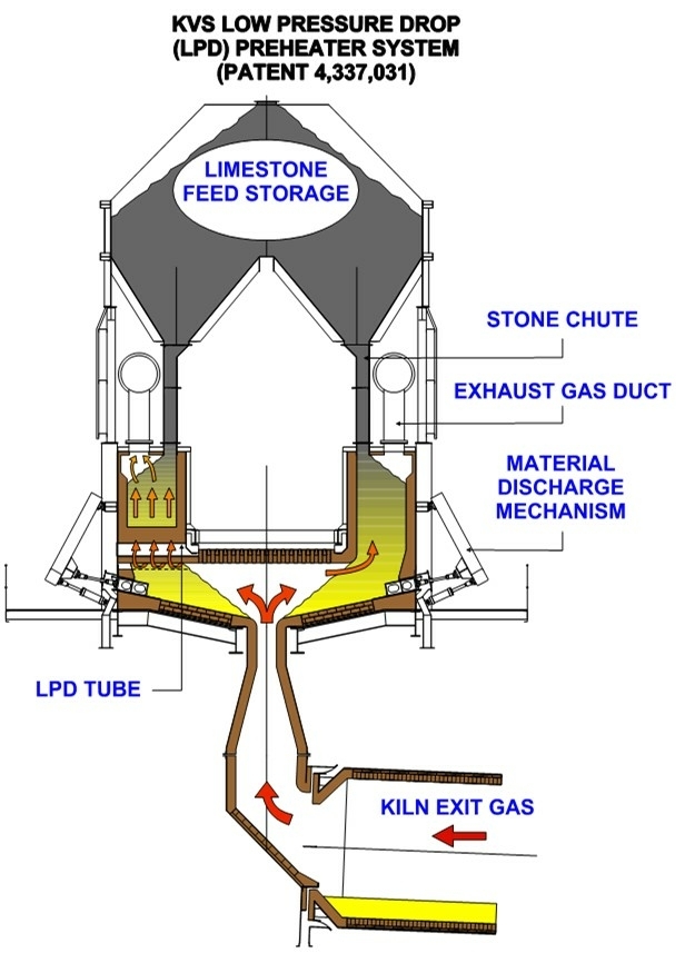
In this publication, a kiln production rate of 400 t/d, i.e. installation of four preheater modules of Polysius/Maerz design, is assumed for the specimen calculations. Modified versions of other shaft preheater types (KVS or Metso Outotec, PSP Engineering, etc.) are also conceivable. Figure 5 shows by way of example a sectional view through a Metso Minerals PH with a rectangular cross-section (200 to 700 t/d, with four to ten pushers).
In rotary-kiln shaft preheaters, all preheater shafts are supplied from a common feed bunker, via simple feed pipes. Kiln throughput is then controlled by pusher stroke and pusher frequency. This, however, does not ensure that every individual shaft is fed with the same quantity of limestone. Caking depositions in the shaft preheater can prove problematical here. Waste-gas temperatures may act as an indicator of differences between the individual shafts. Here, the precondition that every shaft receives the same part flow of waste-gas, is not verifiable or does not, in practice, be verified by means of measurements.
In the rotary kiln, however, the limestone flows from all the individual shafts into only one rotating kiln shell and a certain uneven distribution of the extraction rate of the individual shafts can thus be tolerated.
The situation here is different.
Here, the following are necessary:
Weighing of limestone – all e.g. four preheater shafts must receive the same amount of limestone per unit of time
Pusher frequency must be regulated on the basis of filling level
Airlock function necessary at limestone inlet
In rotary-kiln shaft preheaters, the long feed pipes filled 100% with rock act as a kind of airlock function (see Figure 5). A certain ingress of false air via these pipes is not critical, however, since the (false-air-free) waste-gas temperatures in the rotary-kiln shaft preheater are in any case too high and thus need to be reduced to a temperature tolerable to a waste-gas filter by means of air injection or quenching. Such a rotary kiln charging system must be excluded here, however, as a result of the lack of any facility for weighing.
It appears possible, via the use of known charging systems for shaft kilns for lime, or their combination, to implement a suitable solution, however. The underpressure at the stone level of the preheater shaft is low (see Figure 4). The burning shaft can then be composed of two rectangular shafts, the total shaft cross-section approximately equating to the total cross-section of the preheating zone. Extraction from the burning shaft is accomplished by means of four pushers (for the example of 400 t/d). A pusher control system based on limestone filling level will also be necessary in the two burning shafts.
The design of the airlocks for lump material at temperatures of 830 to 920 °C is critical. Plain slide valves for lump material at 900 °C are, indeed, in use as shut-off valves. These take the form of hybrid designs consisting of high-temperature-resistant steel and refractory concrete grades. The use of such plain slide valves as an airlock component – in continuous operation, in other words – appears to be even more demanding, however. An airlock consisting of two plain slide valves would be conceivable only in combination with synchronised operation of the pusher. An airlock for continuous influx of lump limestone to be burned and assuring operational reliability appears to be scarcely practicable. The cycle sequence is shown schematically in Figure 6. Also important is the fact that the chamber volume of the airlock must be adequately dimensioned – overfilling of the airlock chamber must be avoided. The use of pivoted flaps instead of plain slide valves is also conceivable.
One alternative is the use of a movable box, taking the form of a hybrid design using high-temperature-resistant steel and refractory concrete (Figure 7). The advantage here would be that the refractory-lined box would be carried on an external rail system. Design challenges arise here. The contacting refractory surfaces would, for example, have to be ground perfectly flat. The thrust pressure between the horizontally moving box, which is immovable in the vertical direction, and the counterpieces must not be too high, it must, in fact, be adjustable. The counterpieces can then not be rigidly connected to the inlet chute or to the outlet sockets, but they must nonetheless not be capable of moving in the horizontal direction. Since the new kiln concept requires airlocks, there is an upper limit on the usable particle-size spectrum for technical bulk-material reasons, since the airlocks would otherwise be too large relative to kiln throughput.
The design of the double lances remains critical. The conditions here are different to those of the PFR kiln. In the PFR kiln, the lances in the upper sector of the preheater zone are routed through the kiln wall, which at these points has no refractory lining. Here, the limestone is still at a low temperature. Lance protection cassettes absorb the load exerted by the bed of limestone present. The lances then have, nonetheless, a vertical length of approx. 4 to 5 m, however, i.e. frictional forces between the lances and the bed of limestone exert significant tensile forces on the lances.
With the proposed kiln concept, the lances must be guided through the kiln wall in the zone of the refractory lining, which is, however, state-of-the-art in other kiln types (the lances must be able to follow the movement of the refractory material resulting from its thermal expansion).
More serious is the fact that the limestone bed is, in the vicinity of the lances, at a temperature of between approx. 830 and 760 °C. The use of simple lance protection cassettes is not possible without further design consideration.
On the other hand, only a slight covering of the lances with limestone is necessary, these are short lances. The mechanical load resulting from the forces exerted by the bed of limestone is, therefore, much lower than in the case of the PFR kiln. Above all, these are double lances, which are effectively cooled by the cold primary air.
There arises here a second process-engineering design challenge: Use of the cold primary air for effective cooling of the outer tube, above all in the horizontal part of the lance (geometry: annular gap, necessary primary-air pressure, choice of material, etc.).
Dimensioning of the individual zones
The special feature of the kiln concept examined here is that the geometry of each of the three zones / individual items of equipment can be selected independently. The figures stated below apply to a kiln output of 400 t/d.
In all shaft-kiln types, convective heat transfer between the hot gas and the bed of solids is of importance ([4], [5], [3] and the literature referenced there). As in the publications mentioned, the Nusselt function as per Jeschar 1964 [6] is used. Thermal-energy transfer within the particle is taken into account by means of an approximation equation as per Specht 1990 [7] (keyword: Transient factor). The following bulk-material parameters are of importance:
Equivalent particle diameter (Sauter diameter)
Voids fraction (porosity) of the bed
Preheating zone
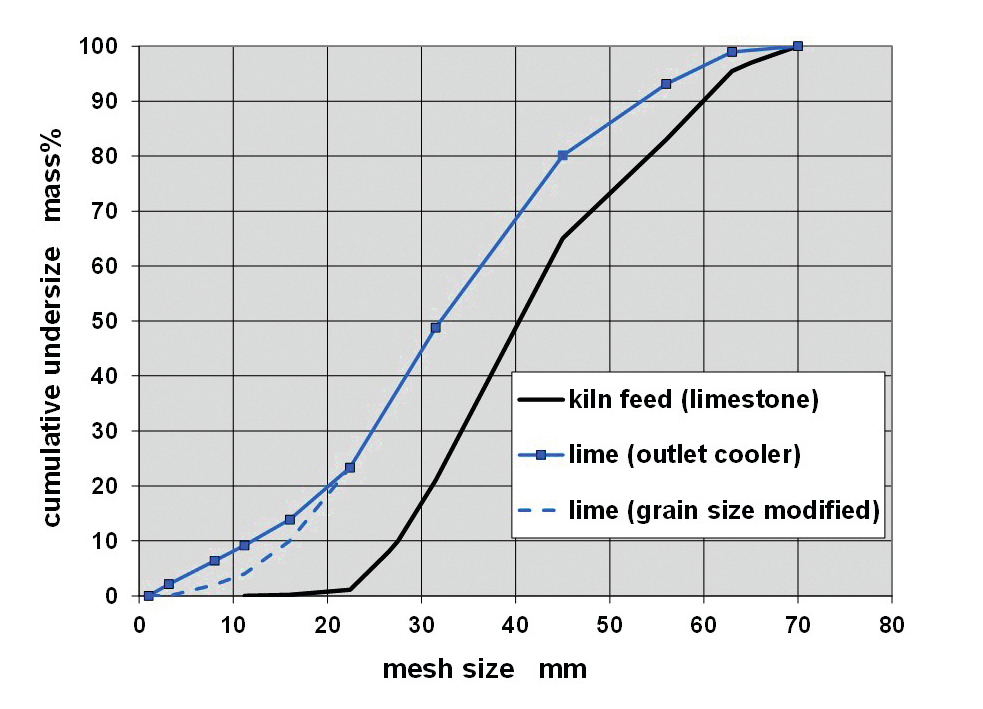
Particle-size distributions as shown in Figure 8 are used. In lime-industry practice, particle-size distributions are generally designated on the basis of the screen-mesh widths used. This, however, frequently does not mean that a kiln feed designated 25 to 70 mm actually has a screen undersize of Q3 (25 mm) = 0%.
Firstly, the Sauter diameter dSt,Ku = 38.8 mm can be calculated from particle-size analysis, assuming spherical shape. A Sauter diameter of dSt = 32.2 mm then results using a particle-shape factor of 0.83 (sphericity as per Wadell).
A voids fraction (porosity) of approx. e = 0.44 can be assumed for this particle-size spectrum. With a limestone density of 2.70 kg/dm³, this equates to a bulk density of 1.51 t/m³.
The specific surface area of the limestone is then SV = 186 m²/m³ limestone.
The following specific heat-transfer surface area can thus be calculated:
⇥(2)
In other words, in a bulk volume of, for instance, VSch = 10 m³, the surface area of all particles is 1040 m² (= AWÜ).
The length of the preheater zone can be calculated to be LVW = 2 m using a total cross-sectional area of the preheater zone of approx. 10.4 m², the bulk parameters mentioned and the data shown Table 2. The cross-sectional surface area mentioned can, for example, be attained using four individual Polysius/Maerz shafts (each individual shaft: 1.80 x 1.44 m). See Figure 3 for temperature plots. The pressure loss of the preheater zone can be calculated using Ergun‘s Law to be DpVW = 15.6 mbar. Ergun‘s Law supplies reliable data provided determination of the bulk parameters has been correct (see, for instance, Stiess [8]). This pressure loss could be reduced by selecting a larger cross-sectional surface area. It is necessary not to fall below a certain pressure loss, in order to assure good gas distribution across the cross-section, however.
Initial partial calcining takes place in the preheater shaft. This must be taken into account in the selection of the height of the preheater shaft.
Cooling zone
It is known from practical experience that the particle-size curve of the run-of-kiln (ROK) lime is significantly shifted toward the fine end as compared to the particle-size distribution of the limestone fed (Figure 8). Here, particle disintegration depends on the geologically induced properties of the limestone, the type of kiln and the manner of kiln operation.
This complicates the dimensioning of the cooling zone. Practitioners hold differing opinions as to where particle disintegration occurs:
Caused by thermal loads as early as in the preheater and/or combustion zone?
And/or as a result of shearing forces in the bed at extraction?
To be on the safe side from a heat-transfer viewpoint, it is necessary to use the particle-size spectrum of the limestone. This, however, results in over-dimensioning of the cooling-zone length and, correspondingly, a high cooling-zone pressure loss. In practice, the data situation concerning the particle-size of ROK lime is, usually, a thin one. In addition, certain fluctuations occur, in other words, a design based only on a few screen analyses, is not reliable. Since the cooling zones in, for example, PFR kilns or ASK, for example, are heavily overdimensioned for geometrical reasons, this problem does not arise in such cases, due to lack of degrees of freedom in dimensioning.
Particularly notable is the geometry-induced overdimensioning of the cooling zone in a PFR kiln. As a result, the superficial gas velocities are so low that it is difficult to achieve good distribution of the lime-cooling air. This is immediately understandable, in view of the extremely low pressure loss of the cooling zone, of merely a few mbar (= difference between pressure cooling air - pressure cross over channel). There have, for this reason, been proposals in recent years for improvement of the flow conditions in the cooling zone of a PFR kiln, see, for example, [9] (in which a number of problems of the cooling zone of a PFR kiln are correctly described).
One benefit of the kiln concept described in this work is the fact that the geometry of the cooling zone can be selected freely to meet the requirements of heat transfer. This is, at the same time, the challenge.
Here, for dimensioning with respect to heat transfer, a modified lime particle-size curve as shown in Figure 8 is used, i.e. a reduced fine-particle content (equivalent diameter increased). A reduced void ratio of e = 0.40 is used, as a result of the wider particle-size spectrum. If a pressure loss from the cooling zone of, for example, DpKZ ≈ 10 mbar is then to be achieved, to force a uniform flow, the shaft cross-section must be selected significantly smaller than the cross-section of the preheater zone (kiln production rate 400 t/d: e.g. for cooling-zone diameter dKZ = 3.0 m, the following results: depth of bed LKZ = 2.05 m, DpKZ = 11 mbar). The residence time of the lime in the cooling zone is then less than 1 hour.
Calcining zones
Conditions in BZ3 are similar to those of a PFR kiln. A more precise design would be possible using, for instance, the Specht/Hallak calculation model [5].
Here, however, the limestone to be burned enters the burning shaft already slightly pre-calcined. The waste-gas enthalpy from cooling from 925 °C to 832 + 5 = 837 °C (initiation temperature of calcining JBG,BZ,E+ minimum temperature difference burning zone DJmin,BZ) is available for pre-calcining in the preheater shaft (see Figure 1, Table 2). A pre-calcining degree of 8.6% results applying the simplification that limestone temperature in BZ1 does not change.
Note: This pre-calcining degree is significantly lower than in the preheater shaft on a rotary lime kiln since there specific waste-gas volumetric flow is larger as a result of the significantly higher specific energy consumption and since gas-inlet temperatures are higher.
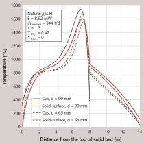
Necessary residence time in the calcining zone is dictated by particle size and hot-gas temperature. For a limestone particle-size spectrum in accordance with Figure 8, i.e. a maximum particle-size of approx. 63 mm and an average surface temperature of the limestone of approx. 980 °C, a residence time of approx. 3.3 h is sufficient. Note: The temperature plots in Figure 3 are qualitative (significant differences between the surface and centre temperatures of the particles).
A shaft length of approx. 6.2 m results if one retains the dimension of 10.4 m² for the preheater zone as the shaft cross-section. The degree of pre-calcining mentioned for the shaft preheater shortens the necessary shaft length. In addition, calcining in BZ2 initially takes place very rapidly – hot air is the most effective means of calcining. The thermal energy for calcining in BZ2 originates from the cooling of lime-cooling air and limestone. Calculation using the equilibrium as per Equation (1) indicates that a degree of pre-calcining of 11.5% is possible if one assumes a temperature difference of 20 °C at the outlet of BZ2. The lime-cooling air then has a CO2 content of 6.3%vol. at a temperature of 755 °C.
Precise dimensioning of the length of BZ2 remains not possible at present. It is apparent, however, that the heat transport of the heat content stored in the kiln charge runs very rapidly toward the decomposition front. In addition, calcining has only just started, in other words, the shell of the lime is still thin. It is possible to state approximately that a degree of calcining of around 20% is possible up to the tip of the lance.
However, it is not necessary to allow calcining to proceed up to equilibrium at BZ2.
Benefits/demerits of new kiln concept compared
to PFR kiln:
Precondition
Design of a reliably operating cyclical airlock for lump limestone at temperatures of up to approx. 920 °C.
Benefits:
Continuous operation
CO2 concentration in waste-gas significantly higher (approx. 40 %vol. at l = 1.12)
Specific waste-gas volume significantly lower (false-air-free, approx. 1.51 Nm³/kg lime at l = 1.12). Smaller waste-gas filter and blower then possible
Reduced kiln pressure loss (lower electrical energy requirement)
Radial fans can be used for lime-cooling air and waste-gas
The coal-metering system is required to operate against a significantly lower counterpressure than in a PFR kiln
Each and every zone can be designed optimally, since the system consists of three individual items of equipment (therefore no problem of distribution of lime-cooling air into cooling zones)
Can be implemented as so-called small-stone kiln for e.g. particle-size spectrum 15 to 45 mm (presupposing correspondingly adapted geometry of the individual zones)
The temperature of the waste-gas from burning zone BZ3 is a good indicator of lime quality
Gravimetric coal metering as in the ASK is not absolutely necessary
Demerits:
Upper limit on kiln feed particle-size distribution (max. approx. 80 mm)
Specific heat demand reacts sensitively to higher air excess factor l
Large cross-section hot-gas pipes necessary
Feed limestone supply to the individual shafts is demanding
As PFR kiln
Specific heat demand 3.6 GJ/t can be achieved (at air excess factor l= 1.12)
Only soft burning of lime possible
Fuel distribution
The author would be grateful for criticism, alternative proposals and suggestions for the design of critical components.
Outlook –
Kiln concept suitable for oxyfuel operation?
The oxyfuel concept is assumed to be known. Pure oxygen is used instead of ambient air for combustion, and the kiln waste-gas consists in the theoretical ideal case exclusively of CO2 (see, for example [1]).
Since the shaft preheater of the new kiln concept consists of not less than two modules and separate items of equipment are installed for preheating, calcining and cooling, the possibility roughly sketched in Figure 9 results. The entire lime-cooling air is routed to one of the two preheater modules or to one part of a number of preheater modules.
The lime-cooling air is thus used directly for preheating of the limestone and is released after dedusting into the surrounding area. It is quite apparent that only a part-flow of the limestone can be preheated using the lime-cooling air. In this context, the limestone can be preheated in this section of the shaft preheater only to approx. 700 °C, since calcining would otherwise start, i.e. the cooled air flowing off into the environment would contain a certain CO2 concentration.
This would have a number of consequences.
Partial calcining in the burning shaft using hot lime-cooling air is omitted (no BZ2).
In theory, the necessary flow of pure oxygen could be fed only via the double lances, since its standard volumetric flow amounts to only 21% of the flow of combustion air during normal operation (oxidising agent: air). The powdered fuel can be conveyed using CO2 removed from the kiln waste-gas downstream the filter.
There result the usual two basic problems of oxyfuel operation:
Extremely hot flames
Gas volumetric flow drops extremely, especially in the burning shaft, i.e. convective heat transfer would be severely reduced using a non-modified shaft geometry
As in other oxyfuel concepts for shaft-type kilns for production of lime [1], it will thus be necessary to recirculate a part-flow of CO2. In this arrangement, the main flow of recirculated CO2 would have to flow into the space above the bed of limestone in the burning shafts. Since the waste-gas downstream the filter (CO2 rich gas) has only a temperature of roughly ≥ 200 °C, however, the CO2 will need to be heated to approx. 900 °C. Otherwise, the limestone leaving the shaft preheater modules would be cooled down again. The empty space above the limestone bed is a perfectly usable burning space. Alternatively, the recirculating CO2 could be heated up in a special channel burner before entering the burning shafts.
It may also be necessary to restrict the combustion temperature by admixture of a part-flow of CO2 to the pure oxygen entering via the lances.
Yet further theoretical development is needed for the drafting of an oxyfuel concept for the kiln process proposed here.
What can be stated even now:
Benefit: No high-temperature gas/gas heat-exchanger is needed (such high-temperature heat-exchangers are critical both under investment cost and operating dependability aspects)
Benefit: There is no need to operate the lime-cooling air especially low
Demerit: The two burning shafts would need to be operated in two different ways. One burning shaft would be charged with non-pre-calcined limestone preheated to approx. 700 °C. The other burning shaft would receive limestone at approx. 900 °C which has also been scarcely pre-calcined (the waste-gas from the burning shaft now has a CO2 content of practically 100%, and pre-calcining in the shaft preheater is therefore only slight).The differing fuel feed to the two burning shafts should be practicable in a continuous process, however.
Demerit: Two filters will be needed
Since a good 50% of the limestone is preheated with lime cooling air, the exhaust gas mass flow to those VW modules that are fed with exhaust gas must not be too high, as otherwise the specific heat energy demand of the kiln increases too much. This gas flow depends on the mass flow of recirculated CO2. The shaft geometry of an oxyfuel kiln will therefore probably diverge from that of a “normal kiln” (oxidising agent: air).
The energy balance of an oxyfuel version of the kiln can be stated only after the performance of process calculations.
Überschrift Bezahlschranke (EN)
tab ZKG KOMBI EN
This is a trial offer for programming testing only. It does not entitle you to a valid subscription and is intended purely for testing purposes. Please do not follow this process.
This is a trial offer for programming testing only. It does not entitle you to a valid subscription and is intended purely for testing purposes. Please do not follow this process.
tab ZKG KOMBI Study test
This is a trial offer for programming testing only. It does not entitle you to a valid subscription and is intended purely for testing purposes. Please do not follow this process.
This is a trial offer for programming testing only. It does not entitle you to a valid subscription and is intended purely for testing purposes. Please do not follow this process.