Selecting steel anchors for monolithic refractory linings
Part 1: Basics
Summary: The correct selection of steel anchors for monolithic linings is critically important as the integrity of the anchor in a refractory lining is one factor determining the life of the lining. To more accurately determine stresses in refractory anchors, numerical analyses must be carried out. Creep rupture stress and oxidation rates are two critical parameters that need to be taken into account. Part 1 of this article focuses on the basics, Part 2 on major failure mechanisms.
1 Introduction The reliability of stainless steel refractory anchors in refractory lined process vessels is becoming more critical as companies pursue greater efficiency and safety. Therefore understanding the failure mechanism of stainless steel refractory anchors is the key to improved production efficiency and better safety. The most common refractory anchor failure is at the interface between the hot face and insulation layer.
The poor performance of ceramic anchors has meant that stainless steel anchors are relied upon for maintaining the integrity of the refractory lining. Thus in...
1 Introduction The reliability of stainless steel refractory anchors in refractory lined process vessels is becoming more critical as companies pursue greater efficiency and safety. Therefore understanding the failure mechanism of stainless steel refractory anchors is the key to improved production efficiency and better safety. The most common refractory anchor failure is at the interface between the hot face and insulation layer.
The poor performance of ceramic anchors has meant that stainless steel anchors are relied upon for maintaining the integrity of the refractory lining. Thus in high temperature environments, greater than 1000 °C, the selection of an appropriate anchor material is vitally important. Equally important is consideration of the load condition that is imposed on the anchor over the time in service.
In the design of static refractory structures the most common selection criteria is the published scaling temperature in an oxidization environment, i. e. the higher the operating temperature generally means that a stainless steel with the highest scaling temperature is selected. However, there are other factors in the design phase that need to be considered, including creep rupture, oxidation and yielding.
It has been found that failure of refractory linings, i. e. steel anchors, is due to yielding or creep rupture of the steel at the interface zone. This is due to the combination of stress and high temperatures at that location. Given a high enough stress, the anchor material will yield in a short amount of time (e. g. minutes), or at lower stress levels, the anchor will deform and fracture due to creep mechanisms over a longer time (e. g. hundreds or thousands of hours).
The current approaches to anchor design and spacing which have been developed from experience and applied “rules of thumb” are inadequate and fundamentally incorrect. Setting anchor spacing as a multiple of lining thickness should not be used. This paper shows that designing anchor spacing and anchor material selection must be undertaken by accounting for process temperature, corrosion of steel, lining weight, creep rupture and thermal strain on the anchor steel. The appropriate anchor spacing and anchor thickness can then be determined.
2 General refractory anchor failures
The integrity of refractory linings in process vessels relies on the anchoring system. Yet even with the latest analytical techniques, the failure of steel refractory anchors is still a serious problem confronting engineers and operators.
Failure of steel refractory anchors in static process vessels, particularly in two-layer systems (insulation and hot face) is still a major concern for industry, resulting in the loss millions of dollars in downtime. Three dominant failure modes of the anchor steels exist and can be described as oxidation, creep rupture and yielding of the steel. In a dynamic process, cyclic loading that may cause fatigue failure of the anchor must also be considered.
Oxidation of the steel is a result of exposure to an air or process gas environment and depending on the alloy of the anchor, the rate of oxidation will generally increase as the temperature increases. Creep rupture is due to the combination of a load on the anchor, for example the weight of the refractory castable and/or the thermal load during operation, and the temperature of operation of the anchor. Creep rupture stresses are normally reported for 1000, 10 000 or 100 000 hours of operation at specified temperatures. The combination of stress and temperature will result in the ultimate failure of the material. A higher load and/or higher temperature would result in the expected time to failure decreasing.
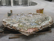
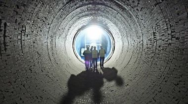
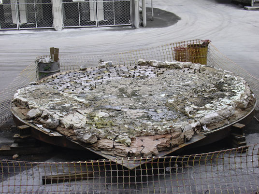
Yielding of anchor materials is due to excessive load applied to the anchor during operation. It is normally associated with movement of the hot face castable due to missing or incorrect support and/or restraint of the castable. Figures 1 and 2 show two failure modes as described above.
The bonding of the insulation and hot face concretes is poor at best and differences in dilatometry characteristics between the two materials means that the hot face can move separately to the insulation layer. The fact that the insulation has a high thermal resistance means that the anchor operates at high temperatures at the interface. Thus the mass of refractory and thermal strains in this high temperature zone and the mechanical properties of the anchor material at the temperature of operation is important.
It is necessary to consider the described failure modes in combination in the design of refractory linings. Unfortunately, creep, thermal strain and oxidation can occur simultaneously which means one factor cannot be considered without also taking the others into consideration. Thus to select an anchor material on scaling temperature alone can lead to premature failure of the refractory system as it does not consider the other factors.
3 Selecting steel anchors – current methodology
Higher process gas temperatures normally means a more exotic alloy (with higher alloy content) is chosen. The most common alloy selected for conditions greater than 1000 °C is 310 stainless steel (310 ss). However, other alloys used include 253 MA, DS alloy and Inconel 601.
Both 253MA and 310ss have a high scaling temperature in an oxidizing atmosphere, reported to be 1150 °C [1]. It is well known that these alloys suffer from sigma phase for-
mation in the temperature range of 550 °C to 920 °C. Sigma phase affects the steel in two ways: firstly, it lowers the oxida-tion resistance (as chromium has been removed from the solution to form the sigma phase) and secondly, it significantly lowers the impact resistance at temperatures below 200 °C. The other alloys also have a scaling temperature equal to or less than 310ss.
The Special Metal Corporation [2] claims that the DS alloy is resistant to the sigma phase and can be heated indefinitely within the 600 °C to 920 °C range without fear of sigma phase embrittlement. However, our research has shown that the DS alloy can form a chromium rich second phase similar to the sigma phase, if not actually a form of the sigma phase and become embrittled at ambient temperature. Published data for 310 stainless steel and DS alloy shows that there is a slight difference in mechanical properties (Table 1). There is no difference in the material service temperature.
4 Spacing of anchors The spacing of refractory anchors has generally followed a “rule of thumb” or empirical formulas. In practice anchor spacing tends to be in the range of 200 mm to 350 mm and orientation of the anchor is offset by 90 ° or some angle. If there are insufficient anchors then the risk of sections of the refractory being unsupported increases and if too many anchors are installed then the risk of poor refractory consolidation or cracking increases. When overhead refractory work is carried out the spacing of anchors is generally set at approximately 200 mm.
An often repeated industrial “rule of thumb” for spacing is three times the lining thickness to maintain a sound refractory lining. The aim being that when the refractory cracks the likelihood of a piece of refractory falling out is very rare. The other function of anchors is to hold “green” refractory in place, particularly in the overhead position, to prevent the material from slumping or falling off during installation. However, if anchors are too tightly spaced then shadowing (poor consolidation) can occur which can be very detrimental to lining integrity.
Laha [5] reported that anchor spacing depends upon the shell or vessel configuration, anticipated operating atmosphere, lining material and its thickness, imposed load and severity of stress due to vibration, etc. Small diameter cylindrical vessels lined with castables may often be self‑supporting. According to [5] the minimum spacing for thin lightweight linings would be 150 mm centres to a maximum of 300 mm to 450 mm centres in thick heavy linings. The Deutsche Gesellschaft [6] states that anchor spacing should be in the order of 1.5 to 2.5 times the lining thickness.
In [7] the anchor spacing for a roof is related to the following empirical equation,
la = a ✻ 0.067 ✻ y
kgfref
where a is the anchor diameter, y is the anchor material yield strength at temperature and kgfref is the weight of the refractory.
Even using this formula the anchor spacing can easily be over estimated. Banerjee [8] has stated that the anchor spacing is dependent on the lining configuration, temperature, lining material and thickness, with anchor spacing varying from 150 mm for lightweight refractories and 450 mm for thick heavy linings.
Laha [5] reported that anchors with equal legs expand equally and can push the material away from the shell, eventually causing shear planes to develop. This problem can be avoided in the case of low‑ to medium‑temperature applications by making the legs of a V anchor unequal. Similarly, a Y anchor with unequal and crimped/corrugated legs allows expansion to occur in various directions, thereby reducing expansion outward from the lined shell.
Chen et al [3] studied a refractory‑lined cylinder with rigid anchors (steer-horn with no coating, or tip coated only) and some flexible anchors (including S‑bar, fully-coated steer-horn, and the proposed spring-shaped anchor). Two heat cycles were applied to the inside face of the lining. The test results indicate that those anchors considered as “flexible” anchors, such as the spring-type anchor and S-bar, have shallower cracks nearby; this would seem to indicate the superiority of those anchors over those of rigid type in a hot-shell lining installation.
The general rule of thumb and guidelines that relate spacing to hot-face thickness are fundamentally incorrect. By stating that anchor spacing should be a multiple of the hot-face thickness means that the spacing should increase with thickness. This means that as the mass of material increases the stress on an anchor will also increase for the same size anchor. Such an approach will obviously lead to anchor failure, particularly at the interface where elevated temperatures mean the anchor will have lower mechanical properties. Anchor spacing needs to be stress based, i. e. the interface temperature, mass of refractory supported by the anchor, anchor material type, oxidation rate, creep rupture strength and thermal strain should be used when determining anchor spacing.
5 Anchor tips and cover There have been a number of theories about the depth of material cover over anchor tips. According to [5] the anchor penetration into the lining should amount to a minimum of of the lining thickness. However, it is generally accepted that the cover over the anchor tip should be 25 mm to 30 mm. For thick linings (> 200 mm) Laha [5] also reported that anchor cover varies from 40 mm to 60 mm. Plibrico [7] recommend an anchor tip cover of 1/4 lining thickness for a roof and lining thickness for a vertical wall. Banerjee [8] published the information that the normal practice is 25 mm cover between the hot face and the anchor tip.
It is believed that the use of plastic tips on anchors assists by accommodating differential expansion between the refractory and anchor, thus reducing cracking or spalling. Laha [5] reported that this practice may reduce the overall holding power and strength of the anchoring system, while Chen et al. [3] reported that coating the anchor tip can generally reduce the pushing effect of the anchor.
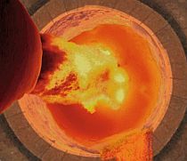
This investigation has studied the damage of the refractory around the anchor tip zone and the condition of the anchor tip itself. It has been found by analysing samples (visually and metallurgically) taken from service that plastic tips in an oxidizing environment significantly increase the degradation of the anchor in that area. Figure 3 shows the effect of plastic on the oxidation of the tip.
Inspection of numerous refractories with and without plastic tips on the anchors has found little visual evidence of damage to the refractory concrete due to differential expansion. Numerical modelling has also been undertaken to evaluate the likelihood of cracking in the refractory under thermal load. In this case numerical analysis of refractory lining structures has been undertaken using non-linear fracture mechanics software ATENA [9], which is specifically designed for reinforced concrete materials and is ideally suited for the analysis of refractory structures with steel anchors. Typical refractory profiles with 8 mm diameter anchors have been studied and it has been found that the anchor tip when encased in the hot face refractory is in compression (provided there are no voids around the anchor) and cracking at the anchor tip rarely occurs.
Figure 4 shows the results of a numerical analysis of a two-layer refractory lining. The hot face strength is f’cu = 80 MPa and insulation layer strength is f’cu = 4 MPa. The temperature of the hot face is 1107 °C and the shell is 157 °C. The anchors (8 mm diameter) modelled are reinforcement bars with temperature applied. The analysis shows that cracking of the hot face concrete around the anchor tips did not occur. The analysis results are in-line with our visual observations. It is concluded that the use of plastic tips on anchors does not reduce cracking of the hotface concrete around the anchor tips. In fact, the use of plastic tips will increase the oxidization/carburization of the anchor tip.
Überschrift Bezahlschranke (EN)
tab ZKG KOMBI EN
This is a trial offer for programming testing only. It does not entitle you to a valid subscription and is intended purely for testing purposes. Please do not follow this process.
This is a trial offer for programming testing only. It does not entitle you to a valid subscription and is intended purely for testing purposes. Please do not follow this process.
tab ZKG KOMBI Study test
This is a trial offer for programming testing only. It does not entitle you to a valid subscription and is intended purely for testing purposes. Please do not follow this process.
This is a trial offer for programming testing only. It does not entitle you to a valid subscription and is intended purely for testing purposes. Please do not follow this process.