Redundancy is not equal to availability


Redundancy is nowadays the keyword when it comes to drive systems for large vertical roller mills. Different gear manufacturers have developed new drive systems. This development is clearly driven by the high power demand of large and very large vertical mills and by the torque limitation of the bevel stage in conventional gearboxes as described in many other articles.
1 Introduction
The newly developed drive systems can be split into two different groups:
Multiple drive solution: This group supplies the required drive power by a multiple of drive systems. This makes it possible to reduce the dimension of each drive train and with it to bypass the challenges presented by the manufacturing of large bevel wheels.
Integrated motor solution: This design is based on the idea of substituting the bevel stage, which is the power-limiting element, and reducing the complexity of the entire drive system.
Manufacturer of drive systems belonging to the first group claim that...
1 Introduction
The newly developed drive systems can be split into two different groups:
Multiple drive solution: This group supplies the required drive power by a multiple of drive systems. This makes it possible to reduce the dimension of each drive train and with it to bypass the challenges presented by the manufacturing of large bevel wheels.
Integrated motor solution: This design is based on the idea of substituting the bevel stage, which is the power-limiting element, and reducing the complexity of the entire drive system.
Manufacturer of drive systems belonging to the first group claim that their systems have integrated redundancy and therefore have the best customer benefit. But what exactly does redundancy mean?
In a technical content the term “redundancy” is understood as the presence of additional resources with the same or at least similar functionality as the primary system. One talks about cold redundancy when the additional resources do not contribute to the service in normal operation and hot redundancy when they do contribute. Redundancy is used to increase the reliability and availability of a technical system to ensure crucial processes (for example emergency power generators in hospitals) or for processes where unexpected downtimes are very costly (as in cement production).
If the availability of a technical system should be increased or ensured by redundancy then it is necessary to investigate the process in detail. The aim is to cover the most crucial and vulnerable sub-systems with additional recourses and hence reducing downtime in the case of unexpected failure of this sub-system. In conventional drive trains of large vertical roller mills the most crucial element is the bevel stage with its bearings.
The down side of the coin of a redundant system is always increased maintenance due to the complexity of the system and often reduced efficiency. Providing additional resources is equal to increasing the number of rotating and wear parts and the monitoring of them. In a drive train for VRMs the number of bearings and tooth contacts is a good indication to illustrate this.
2 Multiple drive solutions
At a first glance the multiple drive solution covers exactly the above-mentioned idea of providing hot redundancy. In case of failure of one system, the operation can continue with only a short interruption for disengaging the damaged drive module. When analyzing the solutions provided by different suppliers, huge variations in the level of redundancy can be seen.
2.1 Siemens Multiple Drive
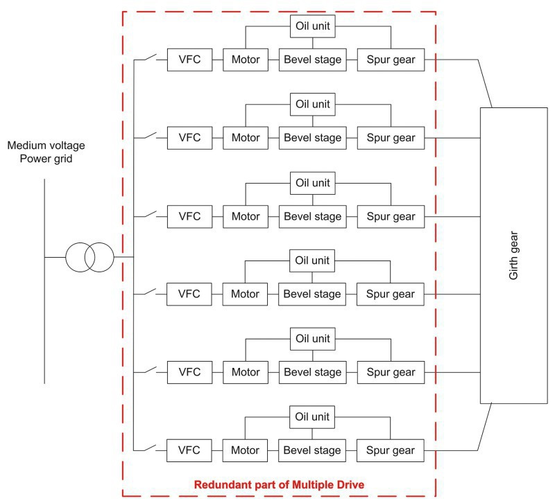
Depending on the required drive power the Multiple Drive by Siemens is supplied with 3 to 6 drive units. All units are engaged into a central girth gear which is connected to the mill table. One drive unit consists of a horizontal mounted electrical motor, a highly flexible coupling, a bevel helical gear with lubrication unit and the corresponding power supply (Figure 1).
The bevel stage, identified as the most crucial element, is in this concept much smaller, compared to conventional drive units because its design power is equal to the total required power divided by the number of drive units. The idea of redundancy is followed by replacing one large bevel gear stage with 3 to 6 smaller bevel gears and in the case of damage, part-load operation is possible with the remaining drive units.
The price for this redundancy is a notable maintenance effort. Considering six drive modules for very large VRM a total number of 31 rotating parts are built-in, together with 62 bearings, most of them roller bearings with limited lifetime, and six lubrication units. All equipped with filters, pumps and valves, etc. To transmit the power from the motor to the mill table a total number of 18 tooth contacts are needed. In comparison to a conventional drive train with a conventional MAAG gearbox, the WPV type has only 15 rotating, 18 slide bearings with infinite lifetime and 15 tooth contacts.
Even though that mill operation continues if one module is under maintenance the production has to be reduced because only part load is possible with a reduced number of drive modules. Increased maintenance in this case is also a production loss.
2.2 Renk COPE
The COPE Drive produced by Renk uses a different approach. It is based on eight vertical oriented water cooled asynchronous motors, which are partially integrated into the gear casing. The motors are connected via a pinion with a central wheel. The torque is transmitted further through a double cardanic connection into a planetary gear stage equipped with six planets. This arrangement eliminates completely the bevel stage. Based on the required gear ratio between motor pinion and central wheel and the low torque transmitted per motor, the central wheel ends up with a very large diameter compared to the tooth height. Such gearwheels are not common in industrial drive trains (Figure 2).
The redundancy of this drive system is limited uniquely to the motor and a part of the power supply. Because of the high number of motors the design power of these motors is around 1000 kW – a motor size where nobody expects low reliability. The redundancy of the COPE system therefore only affects well-defined components of the equipment while other components like the central wheel exists only once.
The increased number of motors has the same effect on the maintenance effort as previously described. Each motor needs five roller bearings. The central gear stage is designed with a total number of 10 slide bearings. In total the entire system needs 40 roller and 10 slide bearings. With eight motor pinions and six planets in the output stage, COPE has no less than 20 tooth contacts. Regardless of the fact that this system provides only partial redundancy it ends up with no less than 26 rotating parts.
2.3 MAAG MAX Drive
The basic design concept of this drive unit is derived from the lateral drives for horizontal mills. Directly at the vertical oriented motor shaft the torque is divided into two spur gear trains arranged in parallel each meshing with a self-aligning pinion into the central girth gear. The highly flexible coupling on top of the intermediate shaft fulfills three tasks. First, it ensures an equal load distribution between the two gear trains, second the timing of the two output pinions relative to each other can be adjusted and third it guarantees a smooth operation thanks to the damping of torque peaks from the grinding process and preventing of torsional natural frequencies in the operation range. The vertical motor is located outside the mill stand and so available space is not a power restriction of the motor. The required drive power of the largest VRM is provided with only two drive units (Figure 3).
With two drive units the MAX Drive provides symmetric torque to the mill table and is still a simple concept, providing redundancy for the motor and spur gear. It looks for the optimal way between redundancy and low maintenance efforts. The MAX Drive contains in total of 27 rotating parts, 32 bearings and 20 tooth contacts.
3 Integrated motor solutions
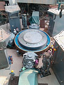
3.1 MAAG CEM Drive
MAAG CEM Drive does not have any redundancy. It follows the way of reducing rotating parts by eliminating the bevel stage and with it providing simplicity. An electrical motor in vertical orientation is placed inside the gear unit lower section and substitutes the bevel stage. It is a very compact synchronous motor with permanent magnet excitation. Built with two radial and one axial slide bearings, it is a 100 % wear-free design requiring a minimum of maintenance. The variable frequency converter supplying the power for the motor also provides variable speed for smooth start up and the possibility to optimize the grinding process. Even the cooling of the motor follows the way of simplification. The motor is cooled with gear lubrication oil provided by one oil system for the motor and the gear section. The losses of this motor are reduced to 1.5 % and with the substitution of the bevel gear stage the overall efficiency is 2-3 % better than any other drive system.
With the CEM Drive FLSmidth MAAG Gear is intentionally foregoing redundancy. By eliminating the bevel stage the entire drive system only contains 13 slide bearings, zero roller bearings and only 14 tooth contacts with 12 rotating parts. CEM Drive is designed to provide availability by simplifying the system – not with complex redundancy.
4 Conclusion
Cement producers who intend to operate cement lines with only one raw and one cement mill need high availability of the entire production line. This includes the drive system of the mills. Recently developed drives claim high availability because of their multiple motor/drive design. A redundant system will provide similar functionality at least for the most critical parts of the process ensuring high productivity. Usually redundancy increases the complexity and maintenance effort of the system as shown in the Table.
The power increase of large mills and the torque limitation of the bevel stage in conventional gearboxes made a new design necessary. With a multiple motor arrangement, the design power of the components of a single drive train is reduced to a manageable size. Applying this idea to the entire drive unit makes the equipment very costly and significantly increases the maintenance effort. Using the multiple motor design only on the motor itself and substituting the bevel stage brings no real advantage in availability because the redundant part of the system is not crucial even though the complexity is increased. Redundancy cannot be equated with availability in every case.
The MAAG CEM Drive is the only system where availability is achieved by substituting the power limiting component and reducing the complexity to the minimum. With the variable frequency drive it provides the highest flexibility with the lowest maintenance efforts.
Instead of seeking availability by using partly redundant drive systems it makes more sense to go for the optimal grinding process provided with the smartest and most efficient drive system.
//www.flsmidthmaaggear.com" target="_blank" >www.flsmidthmaaggear.com:www.flsmidthmaaggear.com
Überschrift Bezahlschranke (EN)
tab ZKG KOMBI EN
This is a trial offer for programming testing only. It does not entitle you to a valid subscription and is intended purely for testing purposes. Please do not follow this process.
This is a trial offer for programming testing only. It does not entitle you to a valid subscription and is intended purely for testing purposes. Please do not follow this process.
tab ZKG KOMBI Study test
This is a trial offer for programming testing only. It does not entitle you to a valid subscription and is intended purely for testing purposes. Please do not follow this process.
This is a trial offer for programming testing only. It does not entitle you to a valid subscription and is intended purely for testing purposes. Please do not follow this process.