Preblending technology for sticky materials – a case study (Votorantim Group)
With an appropriate storage system, a homogeneous mix can be achieved even when sticky materials have to be handled.
For this reason, Votorantim Cimentos has...
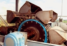
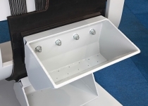
For this reason, Votorantim Cimentos has commissioned Bedeschi for the supply of a clay reclamation and blending system for the Tocantis plant (Tables 1 and 2) using the BEL C machine (Fig. 1). The advantages of this reclaimer are that it has unique features that are not available in any other reclaimers of this type:
A bucket cleaning system that completely removes all the wet sticky material from the bucket ensuring that each bucket can be used to full capacity during reclaiming
A wall cleaning scraper that runs along the entire reclaimer boom which ensures that no material remains on the pit walls
A proprietary wall cleaning software program that allows the wall cleaning scraper to clean the shed wall
The boom has a rigid structure made of steel profiles and is electrically welded. Its upper part is closed by steel sheets to avoid the material falling into the structure and consists of the following components:
chain with links in treated steel
pins for chain fixing in treated steel
running guides of the chain protected by interchangeable steel elements
tension adjusting device for the chain
chain safety factor of 10:1
buckets for material reclaiming
bucket cleaner
The BEL C principle
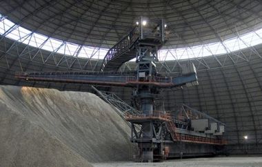
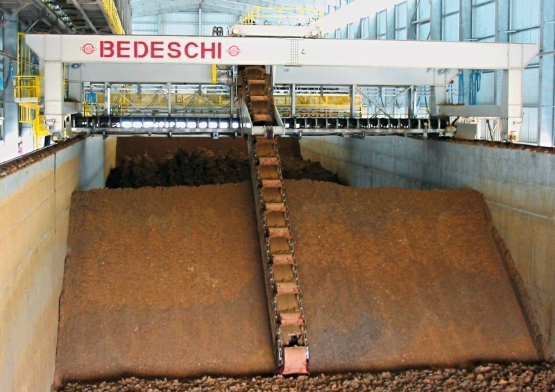
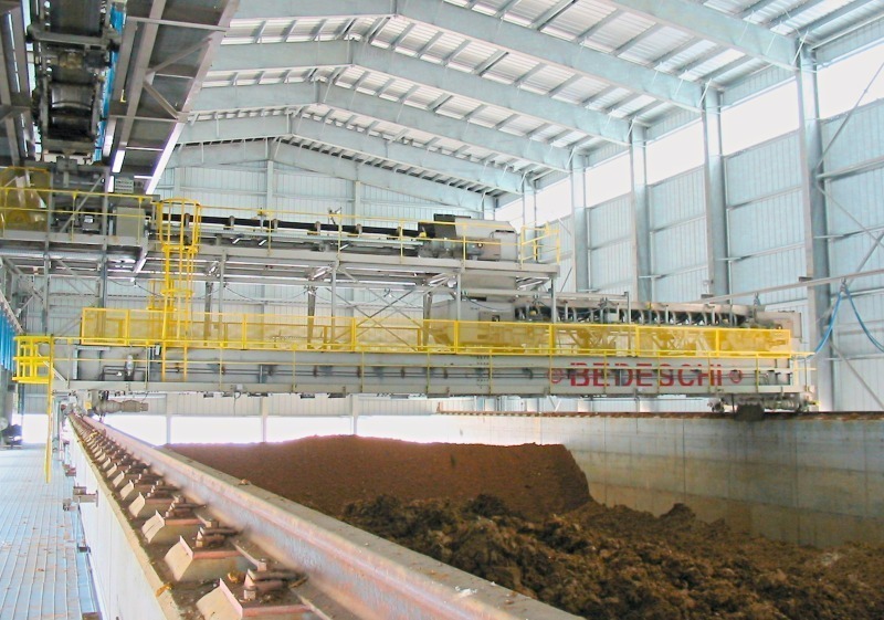
A reclaiming bridge moves on rails on the top of the side walls of the storage container. Due to the bridge and reclaimer being mounted on rails, it is possible to reclaim material from the whole storage surface. Reclaiming is carried out from the bottom of the pile. The buckets discharge the reclaimed material onto the belt conveyor on the reclaiming bridge. This system reclaims material from different layers ensuring that it is well blended. The blending will be discussed later in detail. All the company’s standard machines are controlled automatically and can be operated either:
Locally, (manually or automatically) from the control panel on the machine
Remotely, automatically controlled from the central control room.
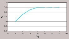
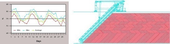
With regards to the chemical characteristics, it is well known that difficulties in efficient blending can be shown as a ratio between: sin = standard deviation of inlet material and sout = standard deviation of outlet material. This is strictly connected to the number of material layers in the storage silos and to the reclaiming system. This matter is treated in the following example. Figure 3 shows the operating mode of a Bel C type stacking and reclaiming system. There are two stacking system possibilities:
Shuttle belt conveyors applied to the shed roof
Shuttle belt conveyors applied to the stacking bridge
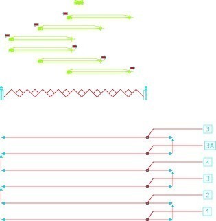
Reclaiming is carried out using the bucket excavator which moves transversally to the deposit, reclaiming the material with a boom from the bottom to the top. The excavator moves between two walls on rails placed on the bridge. After conveying material to the excavator, the bucket excavator can return for another fixed quantity of material and continue reclaiming. Reclaimed material is discharged by the buckets onto the fixed belt conveyor on the bridge. This conveyor then discharges onto the longitudinal belt conveyor which conveys material to the plant. Figure 4 shows the stacking cycle. The different positions of the final shuttle belt conveyor are represented in section. In the lower part (in the plant) are the different layers which correspond to the position of the belt conveyor. If the reclaiming phases are examined, each bucket reclaims an identical portion of each layer, therefore achieving optimal mixing on the belt conveyor.
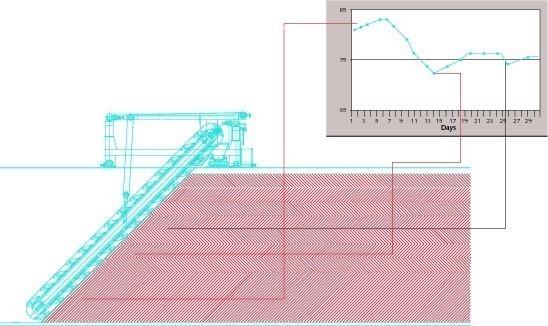
Experiment in a cement plant
Best bucket routing
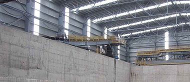
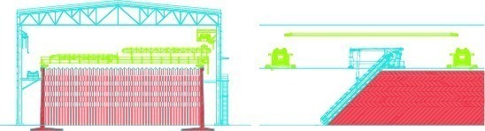
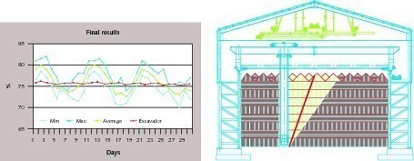
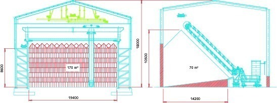
One important point to consider is the cost of the civil work. For this reason the company has tried to reduce the cost in developing a shed. A prefabricated shed completely fabricated with metal has been designed. All the supporting structure is formed with steel beams and the internal walls are prefabricated concrete panels. The Bel C reclaimer provides a very good ratio between the volume stored and the surface used. Figure 8 shows two typical sections demonstrating how, with the same shed height, the volume (which is stored in linear method) is higher with Bel C compared to a lateral reclaimer. This system is currently used in a clay storage yard.
The control system
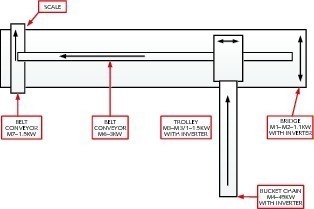
One inverter controlled variable speed motor for bucket drive
Two inverter controlled variable speed motors for trolley travelling.
Two inverter controlled variable speed motors for bridge travelling.
One inverter controlled variable speed motor, for reclaiming belt conveyor rotation
A proportioning belt conveyor, equipped with an inverter controlled variable speed motor and a weighing system with microprocessor unit.
A PLC system for the supervision of all the machine operations and, in particular, for continuous adjustment of the whole system aimed at achieving a regular output.
The control room sends the output set point via the Sinec L2 network.
The machine adjusts the speed of its motors so as to achieve the required output and if necessary, will correct the speed according to the data gathered by the weight of the belt.
Via the Sinec L2 network, the PLC sends the data measured by the scales to the control room for output confirmation.
The output signals are expressed in percentage values related to the maximum capacity of the machine, which, in this case, is 150 tph.
Adjusting system for output regulation
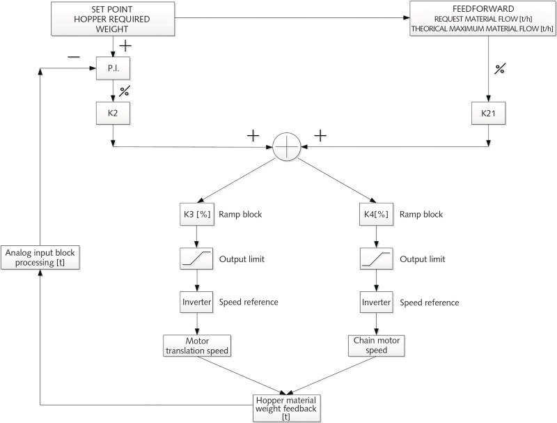
The feedforward term could be considered, to some extent, as a prediction term which is estimated to be suitable to reach the target feedback. In our case, it is calculated as a ratio between the requested material flow (ton/h) and the theoretical maximum material flow (ton/h). In other words, as an example, if the theoretical maximum material flow of the plant is 500 ton/h and the requested material flow is 250 ton/h, it is reasonable to set as the feedforward term a value of 50 %. Subsequently, to adapt this value in order to obtain a value really close to the requested material flow, a K21 adaptative constant is considered. In other words it is not necessary that to have 50 % of the reclaiming capacity the motors have to run at 50 % of their maximum speed: K21 is set for this purpose and it is found, directly, operating in the field with the reclaiming system.
The output reference to the motor inverters is given by the sum of the feedforward term and the output of a PI controller. As could be seen starting from the bottom of the logical scheme, from the weighing system installed in the plant, the hoppermaterial weight feedback is measured, which is reasonably filtered before entering into the controller, in order to have an almost bumpless signal, which is then given as input to the PI controller, together with the hopper weight setpoint. At this point, the PI controller calculates the hopper weight error and acts with its proportional factor Kp and the integral factor Ki. The output of the PI controller is then multiplied by an adaptative constant K2 and this term is, then, added to the feedforward term.
Starting from this block sum, the thus calculated regulation value is then sent to two different blocks, one for the chain motor speed reference calculation and one for the motor translation speed reference calculation, where it is first ramped (K3 & K4: This is a precaution if, for any reason, the regulation value changes in big steps. The reference is in any case ramped to the final value) and then is limited to a minimum and a maximum value (to avoid nonsense values of the inverter speed reference). Subsequently the value is sent to the chain motor inverter and the translation motor inverter, so closing the loop regulation.
Überschrift Bezahlschranke (EN)
tab ZKG KOMBI EN
This is a trial offer for programming testing only. It does not entitle you to a valid subscription and is intended purely for testing purposes. Please do not follow this process.
This is a trial offer for programming testing only. It does not entitle you to a valid subscription and is intended purely for testing purposes. Please do not follow this process.
tab ZKG KOMBI Study test
This is a trial offer for programming testing only. It does not entitle you to a valid subscription and is intended purely for testing purposes. Please do not follow this process.
This is a trial offer for programming testing only. It does not entitle you to a valid subscription and is intended purely for testing purposes. Please do not follow this process.