Burn-out characteristics of lumpy
secondary fuels and requirements for the design of calciners in the cement industry


 Gas velocity in the separator [m/s]](https://www.zkg-online.info/imgs/1/4/6/9/6/7/0/Process_Mersmann_Bild_2-bfc143932c65fe4e.jpeg)


A productive procedure for characterizing the pneumatic and combustion behaviour of lumpy secondary fuels is described. This can be used for calculating realistic flow and combustion processes.
1 Conventional design of calciners in the cement industry
Calciners were introduced into the thermal lines for producing cement clinker in the second half of the last century and have brought about a substantial advance in technology for the cement industry, resulting in significant increases in performance of the kiln lines [1]. Since then many improvements have been proposed for this technology and implemented in product innovations [2-6].
As already described in [7] the fundamental idea behind calciner technology is based on the finding that the most energy-intensive process step in the...
1 Conventional design of calciners in the cement industry
Calciners were introduced into the thermal lines for producing cement clinker in the second half of the last century and have brought about a substantial advance in technology for the cement industry, resulting in significant increases in performance of the kiln lines [1]. Since then many improvements have been proposed for this technology and implemented in product innovations [2-6].
As already described in [7] the fundamental idea behind calciner technology is based on the finding that the most energy-intensive process step in the entire clinker burning process, the expulsion of CO2 from the limestone, takes place most efficiently in a gas-solids suspension. The preheater meal, which is present in this suspension in powdered form and is uniformly distributed in the hot gas flow, experiences the best heat exposure conditions, allowing this energy-intensive process to be carried out as efficiently as possible. A work by Vosteen [8] shows both experimentally and theoretically that the calcination of the finely ground meal particles is completed in less than a second if it is assumed that the temperatures of about 850 ºC needed for expelling the CO2 can be reliably provided. However, in contrast to the laboratory, inhomogeneities occur in industrial plants in the flow, the particle distribution and the temperature fields so that extensive homogenization of these process parameters and keeping them constant over time are the aims of every optimized calciner design and also of the optimized operation of calciner systems.
Calciners were originally designed for use with fossil fuels that were either ground to the usual fineness, if solid fuels such as coal were involved, or were atomized into fine droplets if oils or other liquid fuels were involved. In both cases, and also naturally with the combustion of gas, the location and timing of the conversion of the fuel could be well organized and controlled because the large surface area of the fine particles facilitates spontaneous ignition and rapid combustion.
This situation has changed fundamentally with the use of usually lumpy waste-based secondary fuels that has increased sharply since the 1980s. The cheapness of these secondary fuels is due not least to the fact that they are not processed to the fineness familiar from conventional fuels but have substantially coarser dimensions when they are burnt. However, as a consequence of the input of substantially coarser fuel particles it happens that with increasing size they separate ever more strongly from the gas flow with the result that the flow paths and residence times of the particles and gas deviate increasingly from one another. Even without having to carry out a detailed calculation of the flow conditions in individual cases it is readily understandable that, for example, a fuel particle with edge lengths of several centimetres travels at a different velocity from the surrounding gas and therefore does not experience the same flow paths and residence times as the gas. As a consequence of this separation all the heat and material transport processes at the solid particles obviously also develop completely differently, which ultimately results in great changes in the ignition and burn-out behaviour of the coarse secondary fuel particles.
In many cement plants the maximum quantity of secondary fuel that can be used is determined by this flow and burn-out behaviour of the fuel particles, for which these two behaviour characteristics cannot be evaluated separately from one another. Knowledge of any burn-out rates is useless information without knowledge of the temporary location of the particles that are revealed in the flow behaviour. At the same time, the combustion process is predominantly dependent in all its phases on the temperature exposure of the particle, which in turn depends on the flow paths of the particles in the flow field.
With the increasing use of secondary fuels this gives rise to the problem that the conventional assessment criteria for calciners on the basis of residence time no longer covers the requirements adequately. It is mainly a question of deciding whether it is the residence time of the gas flow that is meant or the residence time of the fuel particles. It must be borne in mind that it is not possible to make a universally valid statement about the residence time of the fuel particles because this obviously depends on the aerodynamic properties of the individual particles and on the specific geometry and flow characteristics that are individual to each calciner. In any case, it can be concluded from the detailed flow calculations carried out by the authors in more than 100 cases that the residence time for coarse secondary fuel particles may definitely be up to 10-times longer than the gas residence time – and even more in individual cases.
Because of the complexity of the linked phenomena the use of lumpy secondary fuels in calciners could for a long time only be advanced by trial and error. The heterogeneity of the waste-based secondary fuels and the physical and chemical complexity of the processes meant that any forecast would be inadequate or impossible. Only in the recent past have models and calculation methods been developed that now permit sufficiently exact calculation of these linked flow and combustion processes while taking account of the heterogeneity of the fuels with respect to particle size, shape, material density, chemical composition and, above all, the distribution functions for these variables in the mixed particulate material [9-11]. A productive procedure for characterizing the pneumatic and combustion characteristics of lumpy secondary fuels that can be used for calculating realistic flow and combustion processes is described below.
2 Pneumatic behaviour characteristics
of lumpy secondary fuels in gas flows
Secondary fuels are normally used in a mixed particulate mass so for adequate characterization the morphology of the entire particulate mass of fuel particles used needs to be appropriately defined.
For powdered fuel it proved sufficient to compile a classical particle size distribution that was determined by sieve analysis. For a primary fuel, e.g. coal, it is sufficient just to describe the particulate mass as a function of the particle diameter. This is because the other parameters that are relevant to pneumatic transport, such as material density and particle shape, can be regarded as adequately homogeneous and constant for the fuel. Because the fuel is comminuted in an upstream grinding process it can be assumed that the slope of the cumulative residue curve can also be regarded as a constant parameter. From the practical point of view it is therefore sufficient to characterize the entire particle population by stating the residue on one sieve (usually 90 µm).
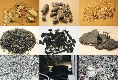
On the other hand, lumpy, waste-based, secondary fuels exhibit severe heterogeneity with respect to particle shape and chemical composition. A fuel does in fact contain powdery constituents as well as fibrous, 2-dimensional film-like, thicker cuboid and 3-dimensional cubical constituents. Furthermore, industrial and domestic wastes contain every sort of combustible constituent, such as plastics-based foams and films, hard plastics, textiles, paper, wood, etc. Their material densities range from 10 kg/m3 for materials or balls of fibre with a high air content to more than 1000 kg/m3 for high density plastics or damp wood.
In spite of this it is now normal practice to describe the secondary fuel particles, in the same way as for primary fuels, just by stating the maximum edge lengths in all three dimensions. A slightly improved approach provides for dividing the particulate mass into three or four classes with different maximum dimensions and specifying the percentages of the total mass for each of these classes. This method comes somewhat closer to compiling a very rough classical particle size distribution but it is still far from adequate for producing an even approximately correct description of the flight characteristics of the particles.
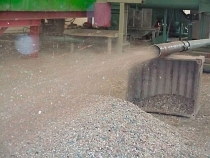
For this reason an analytical method has been developed in recent years that actually places the particle in relation to its suspensibility in a gas flow for which the steady-state sinking speed of the particle serves (also known as terminal velocity) as the descriptive parameter. This is determined by feeding a representative sample of the fuel into a zigzag separator (as for example: ZN 15-80x120 from Bückman) in which the particles are classified by providing a pre-set gas velocity in the flow duct. Those particles that are not entrained by the set gas flow fall out through the coarse material outlet at the bottom end of the separator while the air-entrainable particles are carried out with the gas flow and are separated from it with the aid of a cyclone (Figure 1).
By lowering the gas velocity in stages and feeding the fine material from the previous test back into the equipment it is possible to compile a particle distribution as a function of the suspension velocity (particle velocity distribution). In contrast to the classical particle size distribution this takes account not only of the particle diameter but also of the shape and density of the individual particles. Figure 2 shows the typical behaviour pattern of a representative “fluff” (a solid alternative fuel made of shredded residue) from central Europe as established during an investigative campaign with the Wilhelm Dyckerhoff Institute in Wiesbaden.
It can be seen from the curve that gas velocities of up to 13 m/s are needed for reliable pneumatic transport of an optimally isolated particle in a calciner flow, of which more than 9 m/s is needed for about 10 % of the fuel particles. In the majority of calciners the theoretically determined average gas velocity lies above this value but suspension problems definitely occur in real calciners because local inhomogeneities in the gas flow and the flocking behaviour of the particles encourage the particles to drop out of the gas flow.
3 Burn-out behaviour of lumpy secondary fuels
In addition to the pneumatic behaviour of the particles the burn-out behaviour of lumpy fuel in a gas flow is crucial for the calciner process. Because of the particle size and shape and the material properties the course of combustion of a lumpy secondary fuel particle differs considerably from the combustion of a powdered solid fuel or an atomized liquid phase. The changed surface-to-volume ratio and the inner particle heat and material transport processes slow down all the individual stages of the combustion to a considerable extent.
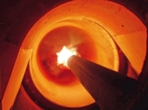
Combustion trials with single particles were carried out in a single-particle laboratory furnace at the LEAT (Faculty for Energy and Plant Technology) of the Ruhr University in Bochum to determine the actual burn-out times of typical secondary fuel particles. The particle was first weighed and then attached to a holder and introduced at time t = 0 into the furnace in which it was surrounded by a flow of air (oxygen content 21 vol. %) at a constant temperature of 1000 ºC. The burn-out was recorded with two video cameras arranged at right-angles to each other. The periods for specific stages in the combustion were then determined in the evaluation of the recordings:
1. Ignition: time until ignition of the particle
2. Intense visible flame: duration of the phase in which the volatiles burn in an intensely coloured flame
3. Weak, visible flame: duration of the phase with less intense flame formation that occurs after phase 2
4. Burn-out of the solid constituents (residual char)
15 different fuel particles, which were obtained by comminution in a shredder with the objective of <30 mm, were analyzed by this method. Figure 3 shows the results for two typical particles.
The upper particle, a label from a drink bottle, represents a classic 2-dimensional particle while the lower one (a commercially available peg) shows a 3-dimensional particle of the type that can normally be found in “fluff”. The investigation has shown that even the 2D particle, which experts generally rate as a high grade fuel particle, requires almost 5 s before it is fully converted. About 2/3 of this time is needed for the release of the volatile constituents. Complete burn-out of the 3D particle, which has 10-times the initial mass of the 2D particle, requires a total of about 38 s. There is just a short phase for intensive release of the volatiles that is superseded by an extended phase of moderate pyrolysis. The volatilization phase lasts, in total, for almost 35 s. The corresponding passages of time for the other particle samples that were investigated obviously varied in accordance with their material, size and geometric properties but common to all the particles was that the ignition and burn-out times were substantially longer than previously supposed.
The burn-out times determined in the laboratory obviously only apply for the homogeneous conditions established in the trial with respect to the relative velocity between gas and particle, the temperature and the oxygen concentration. The trial conditions were established so that they give a good representation of the average conditions in a calciner but each particle is exposed to constantly changing environmental conditions along its flight path in the suspension flow reactor that can both retard and accelerate the actual burn-out time in the calciner. When applying the findings obtained from the laboratory trials for calculating real combustion times in real calciners it should therefore be borne in mind that it is not so much the absolute passages of time that will be set for the combustion in a real calciner but rather that the kinetic parameters of the combustion process determined in the trials should be used, with the real flow, oxygen and heat exposure conditions that actually occur. Through appropriate consideration of these relationships in detailed calculations (numerical flow simulation, CFD) it is possible to make an accurate calculation of the actual exposure of each particle to heat and oxygen in the calciner flow, and therefore of the ignition and burn-out behaviour of the secondary fuels. With the aid of this knowledge it is then possible to design a calciner optimally to suit the local conditions and the requirements formulated by the operator.
4 Requirements for the design of calciners
From the investigations into the pneumatic flow characteristics and burn-out behaviour of lumpy secondary fuels it is possible to make the following main points:
1. The widespread assessment of the suitability of calciners by the so-called residence time is deceptive and unsuitable, especially if this is not related specifically to either the gas phase or the solids. The performance of a calciner is not determined by the residence time of the gas but by the fullest possible conversion of the fuel, so accurate knowledge of the particle residence time and its exposure to heat and oxygen is crucial.
2. The morphology of the particulate mass of secondary fuel must be correctly described for the design of calciners fired with secondary fuels and the calculation of the processes that take place inside them. The aerodynamic properties of the individual particles in a normal secondary fuel mixture differ widely and are determined by their dimensions, shape or form and solid density. The pneumatic behaviour cannot be meaningfully described by the method that is normally used in the industry of specifying the percentages of the 2D and 3D particle sizes. This description of the particulate mass is incomplete and defective. On the other hand, fractionation on the basis of the steady-state sinking speed of the particles in the particulate mass should be used to describe the particulate mass because this variable provides a comprehensive description of the pneumatic behaviour of the particles in the flow.
3. The times required for ignition and burn-out of particularly coarse secondary fuel particles are unexpectedly long. The reaction kinetics parameters determined in the laboratory trials can be used in detailed calculations.
4. For optimum design of a calciner fired with secondary fuels the ideal solution is to calculate the coupled flow, combustion and calcination processes in a sufficiently detailed model with the aid of CFD. Such a model can calculate the burn-out rates separately for different classes of secondary fuels so that specific optimization can be undertaken on this basis.
5. In the majority of cases the maximum usage rate for secondary fuels is determined either by an intolerable CO emission or by an operating problem in the kiln inlet/kiln riser duct area. CO emissions occur mainly through fuel particles of moderate size that are small enough to be suspended in the gas flow but are then not fully burnt out within the not very greatly extended residence time before they enter the bottom cyclone stage. Operating problems in the kiln inlet/kiln riser duct area often occur as a result of an excessive number of coarse fuel particles falling through. When they meet the material bed and become mixed with it they lead to reducing conditions locally with the resulting coating and quality problems. This mechanism can also cause further CO emissions and increase the concentrations of recirculating sulfur and chlorine.
6. The residence time of coarse secondary fuels can be extended many times beyond the average gas residence time by recirculating coarse secondary fuels in the lower part of the calciner. This can be done in special pre-combustion zones in the lower part of the calciner or through an inclined duct within which the coarse pieces fall to the base. They can then pass back on the inclined base to the area above the kiln constriction and become suspended again in the gas flow. This cycle can continue until the particles become so light that they no longer sediment in the inclined duct and finally flow through the calciner via the gas passage to its outlet into the bottom cyclone
7. Suitable and reliable pneumatic transport of lumpy secondary fuels is generally dependent on flow patterns that are often locally distinctive and are specific to the plant with the result that generally valid design guidelines for calciners do not appear appropriate unless the secondary fuels can in turn also be defined in a universally valid and reproducibly standardized form. With the variabilities that are basically inherent in these materials it can therefore be assumed that each application must be individually optimized. A carefully performed CFD study can help to produce a substantial increase in the usage rates for secondary fuels.
//www.aixergee.de" target="_blank" >www.aixergee.de:www.aixergee.de
Überschrift Bezahlschranke (EN)
tab ZKG KOMBI EN
This is a trial offer for programming testing only. It does not entitle you to a valid subscription and is intended purely for testing purposes. Please do not follow this process.
This is a trial offer for programming testing only. It does not entitle you to a valid subscription and is intended purely for testing purposes. Please do not follow this process.
tab ZKG KOMBI Study test
This is a trial offer for programming testing only. It does not entitle you to a valid subscription and is intended purely for testing purposes. Please do not follow this process.
This is a trial offer for programming testing only. It does not entitle you to a valid subscription and is intended purely for testing purposes. Please do not follow this process.