Newly constructed basement reduces ­vibrations

University of Thessaloniki, AGET Heracles, Lafarge Group

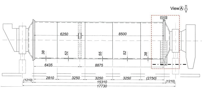
Calculations using the finite element method (FEM) provided a significant optimization to the basement of cement mills. Operation-related vibrations can be reduced in this way.

Introduction

The dynamic behaviour and thus the operational reliability of large mechanical installations such as cement mills can be strongly affected by the basement of their driving units. Increased vibrations, mainly in the region of the two pinion girth gear housing basements of the double mill drive were measured during the operation of a cement mill in the Halkis plant of Heracles General Cement Co (Lafarge Group). These led to excessive damages to the tooth flanks of the pinions. The pinions were replaced without avoiding the intense vibrations in both pinion housings. To detect the...

Introduction

The dynamic behaviour and thus the operational reliability of large mechanical installations such as cement mills can be strongly affected by the basement of their driving units. Increased vibrations, mainly in the region of the two pinion girth gear housing basements of the double mill drive were measured during the operation of a cement mill in the Halkis plant of Heracles General Cement Co (Lafarge Group). These led to excessive damages to the tooth flanks of the pinions. The pinions were replaced without avoiding the intense vibrations in both pinion housings. To detect the reasons for these vibrations it was necessary to describe analytically the static and dynamic behaviour of the mill installation by means of Finite Elements Method (FEM) supported calculations. Based on these computational results, a redesign of the driving pinions housing basements was conducted, achieving a mill operation at a low vibration level, which was ascertained by appropriate measurements.


FEM-description of the initial geometry

of the mill installation

The geometry of the mill installation was described by the Solidworks 2008 software. The ANSYS package was applied as the CAE tool for the structural analysis of the steel basement, and for conducting the static and modal calculations [1]. Employing this software, a 3-D model of the mill arrangement was developed. Detailed 2-D drawings of the individual parts and of the installation were considered for achieving a high accuracy in the FEM simulations. The FE models of the individual parts were assembled in an overall cement mill simulation model. Figure 1 demonstrates the drawing of the side view of the investigated cement mill. In Figure 2, a top view of the motors, the reducers and the driving pinions of the mill are shown. Two motors with corresponding reducers rotate the mill by means of two pinion gear pairs. Moreover, Figure 3 shows the original geometry of the pinion bearing’s housing basement as drawing and photographs.

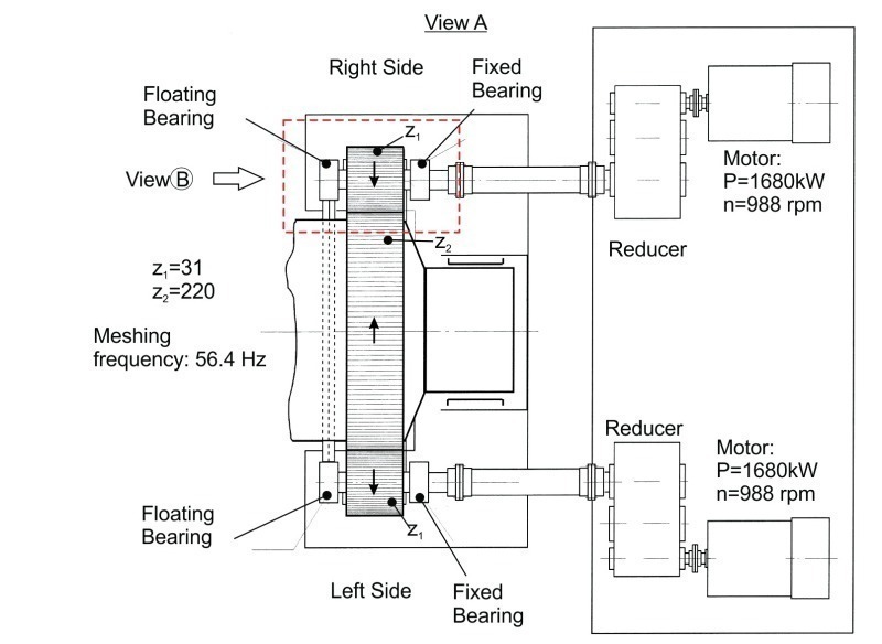
Since elastic couplings are used for the torque transfer to the pinions’ axis, which hinder the transfer of torsional or bending vibrations to the pinions, the reducers and the related transmission shafts were not considered in the created model. In the FEM simulation, the torque of the pinion axis was taken into account as the main load.

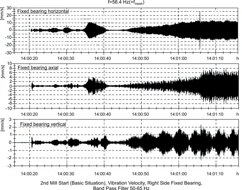
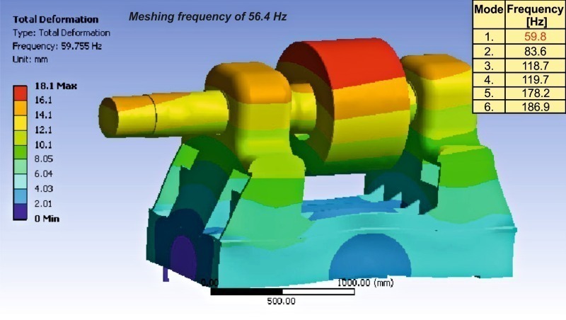
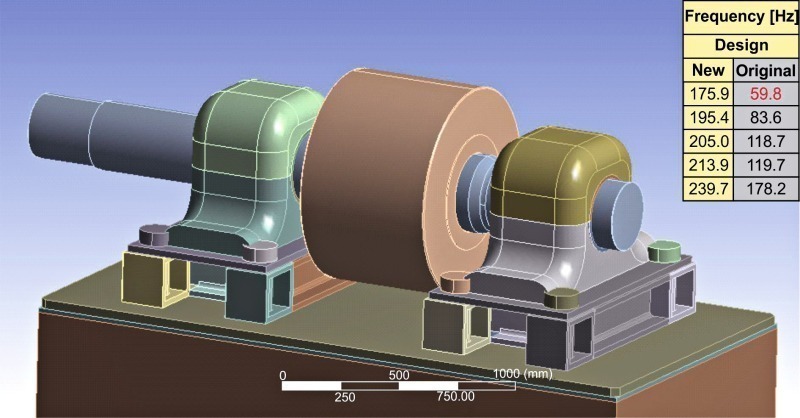
Considering the teeth numbers of pinion and girth gear and the rotational speed of the pinion axis, the meshing frequency of the gear pair was calculated and amounts to 56.4 Hz (Fig. 4). The vibrations in the area of the pinion’s shaft housing were measured in horizontal, axial and vertical directions. A frequency analysis of the time signal of these vibrations revealed a natural frequency of 56.4 Hz which corresponds to the meshing of the pinion-girth gear pair [2, 3].

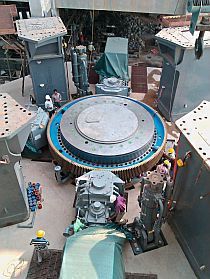
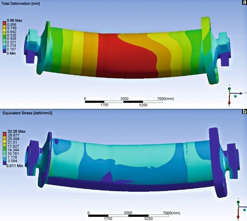
The 3-D model of the mill installation model (Fig. 5a) is created in accordance to the dimensions and the mass distribution in the mill, which is shown in Figure 5b. Geometrical details, with minor contribution to the accuracy of the FE analysis, were omitted to avoid an excessive number of elements in meshing and a consequent increase of the calculation time. The mill was simulated under full load.

The calculated total deformation and the developed equivalent stresses of the mill under the gravity loads are displayed in Figure 6. The deformations and stresses are low and thus, they cannot be considered as parameters leading to wear or other damages to the pinion girth gear pair. More specifically, the developed maximum mill bending deformation of approximately 1 mm in longitudinal direction can be considered, at the existing overall mill length of ca. 15 m, as negli- gible and the occurred maximum von Mises stress of ca. 3.2 daN/mm2 as low [4].

FEM simulation of the pinion bearings’ housing

basement: Describing its dynamic behaviour

Due to the excessive wear on the pinion’s flanks and the elevated vibrations, especially in the region of the pinion’s shaft housing, the geometry at this area was modelled in more detail. A cross section of the pinion shaft with its bearings and housing, which is shown by a dotted line in Figure 2 and its 3-D FE model are presented in Figure 7. The components to the right of the elastic coupling are not included in the model, as already mentioned, since the elastic coupling isolates the pinion shaft from torsional excitations by its driving devices. The filling grade of the basement with concrete was also taken into account (Fig. 7a) and the steel plates for the basement strengthening as well. Eight bolts of a diameter of 48 mm are used to fix the whole construction onto the concrete base [5].
The dynamic behaviour of the pinion bearings’ housing and its base was investigated by conducting modal analysis. The first six calculated eigenfrequencies of this model are displayed in Figure 8. According to these results, the first eigenfrequency of 59.8 Hz lies close to the operational meshing of 56.4 Hz of the pinion girth gear. Since the difference (59.8–56.4 = 3.4 Hz) amounts only to 6 % of the meshing frequency, this difference is not considered as sufficient for avoiding resonance of the mill pinions bearing basements at the meshing frequency of 56.4 Hz. In this way, increased vibrations are expected, which were measured during the mill operation (cf. Fig. 4). The eigenform at the eigenfrequency of 59.8 Hz is also shown in Figure 8. This motion corresponds to a rotation of the whole arrangement around an axis, which lies in the basement’s concrete and is parallel to the longitudinal gear shaft axis.

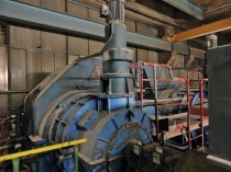
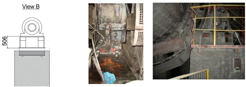
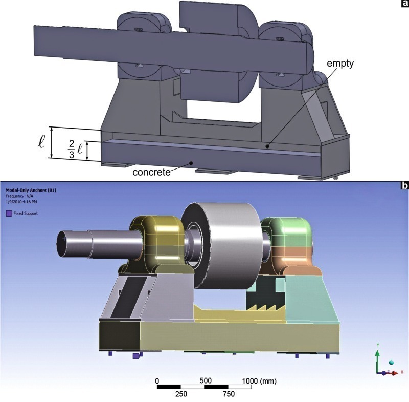
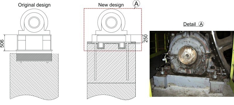
Due to the fact that the excessive wear problems were developed in the region of the pinion’s shaft bearings, the mill manufacturer proposed a solution, often employed in similar installations of other plants. According to this proposal, a V-shaped beam (V-beam) connected the basements of the two pinions. The objective of this construction was to increase the stiffness of the basements for reducing mainly the vibrations level in this area. For investigating the effect of the V-beam application on the system dynamic behaviour, this was modelled considering its original construction drawings.

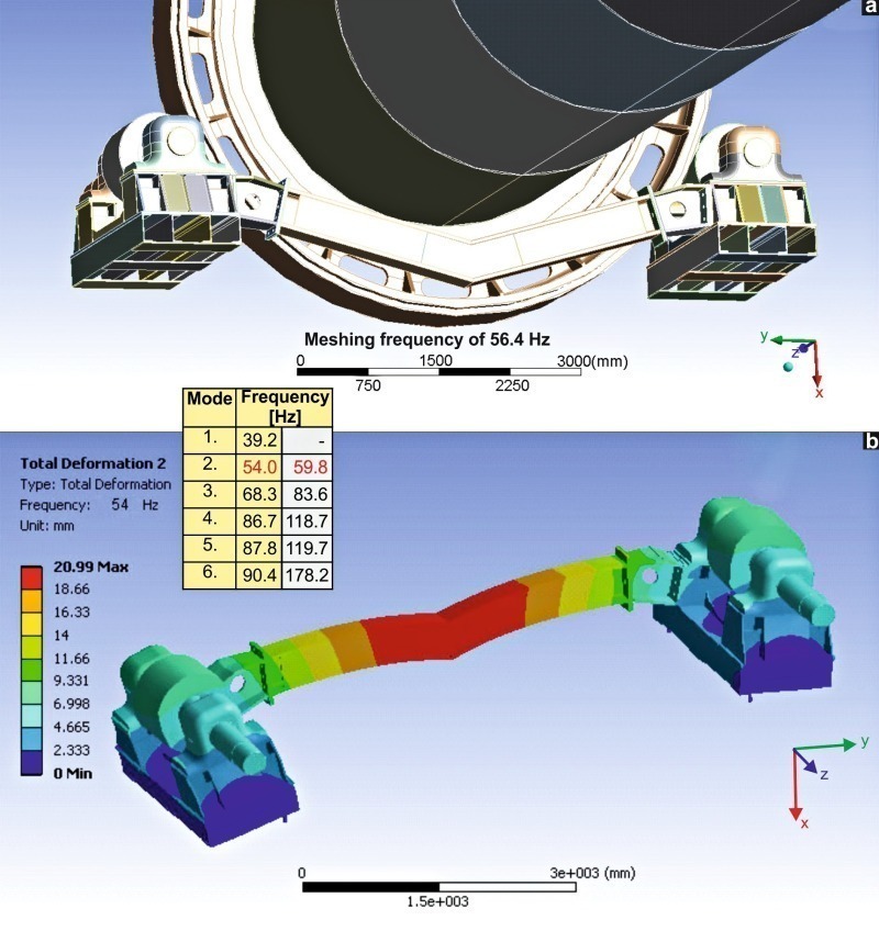
In Figure 9 the V-beam is presented and also its integration into the whole mill installation. In the same figure the calculated eigenfrequencies of the two pinion bearings’ basements, connected by the V-beam, are demonstrated. The application of the V-beam led to a slight reduction of the critical eigenfrequency of the pinions shaft housing without the V-beam connection from 59.8 Hz to 54 Hz (see table in Fig. 9). Moreover, it introduced a new eigenfrequency, the first one, at 39.2 Hz. This frequency is not considered as critical, since it lies more than 30 % far from the pinion-girth gear meshing frequency of 56.4 Hz. However, because of the small distance of the second eigenfrequency of 54 Hz to the pinion-girth gear meshing frequency (< 6 %), the second eigenfrequency is now considered as critical for the appearance of resonance vibrations.

The eigenform at 54 Hz is also monitored in Figure 9. The pinions’ shaft housing and its basement conduct a rotational vibration around an axis, parallel to the pinion shaft, as was the case during mill operation without the V-beam. Thus, the application of the V‑beam is not recommended, since the resonance vibrations at the pinion-girth gear meshing frequency cannot be avoided.


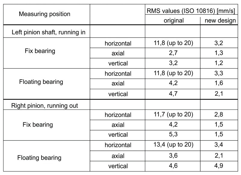
Redesign of the housing basement

for the reduction of vibrations

For improving the dynamic behaviour of the pinions’ shaft housing, its basement had to be appropriately changed. Constructive details of the redesigned pinion bearing’s housing basement and a comparison to the original one are shown in Figure 10. In the new basement design, a lower metal base on the concrete block was applied, which is now elevated respectively for achieving the required height position of the pinion axis. Eight anchors with eight bolts of a diameter of 48 mm were employed for fixing the basement with the concrete blocks and for a smoother load distribution. The FE model of the redesigned pinion’s shaft housing short metal base is demonstrated in Figure 11. Each of the eight anchors has a supporting box and these are connected using HEM beams. To check the effectivity of the proposed basement geometry concerning vibrations’ avoidance, the related eigenfrequencies were determined (see the table in Figure 11). The first eigenfrequency amounts now to 176 Hz, which is far away from possible excitation frequencies, as for example from the meshing one of 56.4 Hz. Thus, a mill operation at a low vibrations level can be achieved. The vibration measurements in different positions at the driving pinion basement, before and after its redesign are monitored in Table 1. It is obvious that the vibrations of the lower and stiffer driving pinions basement are significantly decreased compared to the original layout, corroborating the fact that the implemented solution led to a significant improvement of the mill dynamic behaviour.


Conclusions

The basements of the driving pinions’ bearing housing of a cement mill led to intense vibrations and to pinion flank damages. A FEM-based modal analysis showed that the first eigenfrequency of the pinions’ shaft basement lay close to the pinion girth gear meshing frequency. Moreover, based on the analytical and measurement results achieved, the application of a V-beam, to connect the pinions basements, did not contribute to a vibration decrease. The redesigned driving pinion basement includes a short metal base on an elevated concrete basement for achieving the height position of the pinion axis. The related modal analysis revealed a first eigenfrequency of the redesigned pinion’s shaft housing basement far from the pinion girth gear meshing frequency. In this way a mill operation at low vibrations level could be attained. Appropriate vibration measurements ascertained the achieved computational results.

Überschrift Bezahlschranke (EN)

tab ZKG KOMBI EN

4,99 € / Woche* (Test EN)

This is a trial offer for programming testing only. It does not entitle you to a valid subscription and is intended purely for testing purposes. Please do not follow this process.

This is a trial offer for programming testing only. It does not entitle you to a valid subscription and is intended purely for testing purposes. Please do not follow this process.

Bestellbutton in Angebotsbox (EN)

tab ZKG KOMBI Study test

2,49 € / Woche* (Test EN)

This is a trial offer for programming testing only. It does not entitle you to a valid subscription and is intended purely for testing purposes. Please do not follow this process.

This is a trial offer for programming testing only. It does not entitle you to a valid subscription and is intended purely for testing purposes. Please do not follow this process.

Bestellbutton in Angebotsbox (EN)

Related articles:

Issue 9/2016 C. U. W. KELLER GMBH & CO. KG I ZEMENTWERK BURGLENGENFELD (HEIDELBERGCEMENT AG)

High-precision work for main gear ­replacement on a tube mill

1 Introduction The Krupp two-chamber tube mill at the Burg­lengenfeld cement plant has been in service for about fifty years. It has a diameter of 3.8 m and a length of 14.1 m, thus occupying a...

more
Issue 10/2019 FLSMIDTH | ANNA UNIVERSITY | IIT-MADRAS

Radial run-out prediction of girth gears with dual-mesh pinions by means of finite element analysis

1 Introduction Ball mills are mainly used within the cement and the mining industry for dry or wet grinding a wide range of different materials. Despite the many different applications, the basic...

more
Issue 10/2016 FLSMIDTH | ANNA UNIVERSITY | IIT-MADRAS

Tube mill drive systems – a review

1 Introduction In cement production, tube mills with multi-chambers are traditionally used in either open or closed circuit operations. The process of cement grinding basically includes a grinding...

more
Issue 5/2016 FUCHS LUBRITECH GMBH

Open gear service and documentation by Fuchs Lubritech

Open gears in the cement industry are capital goods requiring very high investments. Regular service as part of the maintenance is the prerequisite for their reliable operation and long service life....

more
Issue 1-2/2017 ONESTONE CONSULTING S.L.

Drives for large vertical roller mills

1 Introduction Vertical roller mills (VRM) have dominated raw materials and coal grinding for many years, and in cement and slag grinding the market share of VRM is constantly growing with larger mill...

more