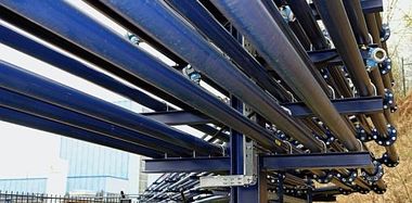
Pneumatic conveying and precise metering of dust
Every firing technician knows that a firing system can only be as good, as regards the flame stability, as its fuel feed. If standardized liquid or gaseous fuels, such as fuel oil or natural gas, are used, the fuel supply can be solved almost unproblematically. The corresponding dynamic pressures are created by means of pumps or compressors and suitable control systems make sure that the utility flows to the burner with a highly constant amount. Thus, the prerequisites exist for a highly qualified burner operation.
Exacting handling of solid fuels
Solid fuels, however, have to be handled...
Every firing technician knows that a firing system can only be as good, as regards the flame stability, as its fuel feed. If standardized liquid or gaseous fuels, such as fuel oil or natural gas, are used, the fuel supply can be solved almost unproblematically. The corresponding dynamic pressures are created by means of pumps or compressors and suitable control systems make sure that the utility flows to the burner with a highly constant amount. Thus, the prerequisites exist for a highly qualified burner operation.
Exacting handling of solid fuels
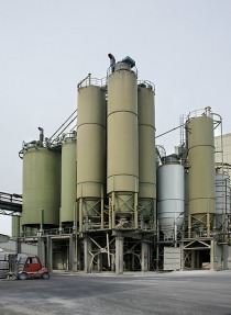
Solid fuels, however, have to be handled differently. If they exist as a pulverulent product in a storage silo, the direct dust utilization in the form of a “simple” further pneumatic transport to the burner is not suitable, if a stable flame behaviour is required. This is due to the individual dust particles, which touch each other at their surfaces, thus causing surface resistance/static friction decisively affecting the flow behaviour of the dust.
It is generally known that the operation of a dust storage silo requires indispensably auxiliary equipment for a reliable dust discharge, such as predominantly vibrating plates or pneumatic aeration systems. Both systems have the same goal, i.e. to dissolve the adhesion resistance between the dust particles and to cause the dust to flow.
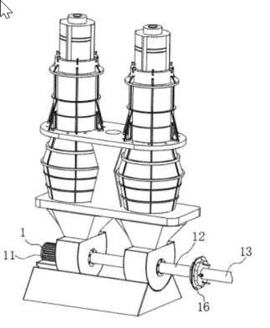
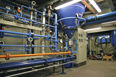
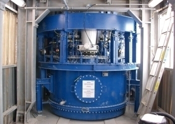
As regards the CT proportioning device (Fig. 1 and 2), CARBOTECHNIK does not make use of the mechanical flow effect but of the pneumatic one. The dust of the container of the CT proportioning device if fluidized by means of air thus acquiring liquid-like properties. Consequently, the basis for an exact proportioning has been created.
Operational principle
The CT proportioning device consists of a cylindrical container, which, depending on the fuel, normally is pressure shock resistant up to 10 bar (according to the pulverized fuel specification). In the lower part of the container there is a fluidized bottom on which the product to be conveyed is stored. If air is pressed in via a blower with a low velocity from below through the bottom, the product is fluidized, i.e. it expands by about one third as opposed to the basic volume and assumes liquid-like properties.
Thus, dusts flow through openings, fill cavities etc. like a liquid. With air throughputs in a specified volume flow range, now the product assumes a very constant density. Depending on the design, one or more horizontally arranged perforated discs (Fig. 3) immerse into this fluidized dust. The holes of such a perforated disc are filled with the fluidized dust in the fluidized bed. The disc is turned into the conveying line where the holes filled with dust are blown out. Now the dust in the conveying line is carried to the target point. The conveying and, at the same time, carrying air is generated by a blower. Special face seal rings are arranged on the conveying line at both sides of the perforated disc to separate the higher pressure stage on the end of the conveying air from the pressure stage inside the container. The face seal rings are pressed on by elastic force and ensure an optimum tightness of the system.
A frequency converter is used to change the speed of the perforated disc and, consequently, of the conveying capacity. It ensures the performance control on the discharge end.
The perforated discs as well as a central agitator in the fluidized dust bed, which effectively prevents the formation of air passages, are driven by vertical shafts, the geared motors of which are arranged on the cover of the casing of the proportioning device. Scavenging air is admitted to the shaft feedthroughs thus sealing them simply and effectively.
The product level inside the CT proportioning device is controlled by means of level sensors. If the level drops down to the refill probe (MIN), refilling of the proportioning container is started, e.g. by means of rotary air locks at the silo inlet or an external screw conveyor. If the MAX probe above responds, refilling will be switched off. An additional safety probe ensures a minimum product amount in the proportioning container.
There are two ways of disposal of the discharged, dust-laden fluidizing air. One way is to lead the air into the dust storage silo via an aspiration line. The silo should always be equipped with a corresponding filter. The other way would be to clean the fluidizing air by means of a top-mounting filter just for this purpose, which is arranged directly on the cover of the proportioning device.
The interior of the proportioning container can be inspected via manholes. Thus, there is access to all inserts.
Metering quality
Perforated disc proportioning is always a volumetric proportioning. Due to an always almost constant density of the fluidized product in the corresponding relevant range of air throughput, this also corresponds to a gravimetric metering with a very good approximation.
If the perforated disc is considered separately, the theoretic metering precision amounts to 100%. The chosen hole pattern ensures that each position of the disc in the conveying line has an equal, free cross-section of the perforation. Fur this purpose, the perforated disc is steplessly frequency-controlled. Therefore, deviations from the 100% of the metering precision can only be generated by the fluidized product itself. This is really the fact in practice. Dusts with a wide particle-size range also have a wide range of effectiveness of fluidizing, considering the air-bonding power of the granular mass. The changed heights of the granular mass in the proportioning container influence the counter-pressure of the blower and, consequently the amount of fluidizing air.
If a highly precise proportioning is required due to process engineering, the amounts of fluidizing air are measured and controlled on the proportioning devices.
A second fact that may influence the metering precision temporarily is the refilling process of the proportioning container. If the following dust is fed too quickly it may affect the fluidized bed temporarily. Frequency-controlled rotary air locks or screw conveyors lead to the required attenuation.
Electric equipment
The CT proportioning device can be equipped in all usual tension levels both on the power and the control voltage end. On the control end three alternatives can be used:
Without control unit - All relevant control signals are cabled in a terminal box arranged on the device. In this case the operator himself has to try to get the correct and admissible control system, from the point of safety engineering.
Control unit with slave module - The control unit including all corresponding control and power elements is arranged in a control cabinet. The hardware is based on the peripheral modular system ET200S from Siemens as well as a frequency converter, type Synamics G120. The operator has to provide for the power supply and a data line. The slave module includes a Profibus DP activation, which is connected to a master control. It is absolutely necessary that this is a fail-safe module F. A Simatic S7 from Siemens is used as software module.
Stand-alone module - It has the same function as the above slave module. However, instead of the Profibus activation, a fail-safe CPU is used. Therefore, a Siemens Simatic PLC is not required as master control and a fail-safe design is not required either.
Metering configurations
With the CT metering system, not only one, but many supply points can be reached from one proportioning container. The proportioning units in a system can be operated absolutely independent from each other and controlled as regards the performance. Figure 4 shows exemplarily some possibilities of a configuration of a CT proportioning device.
Range of application
The CT proportioning device has been developed and designed as individual machine to be installed in a complex overall plant as defined by the EC guideline 98/37/EG, which should be applied.
The CT proportioning device has been designed to be used in explosion protection fields. Components and instruments are used as standard, which are suitable for the interior of the machine (direct dust range) to be used according to the requirements of the ATEX zone 20 and in the exterior according to the ATEX zone 22. Any possible configuration can be executed for the special case of application.
Fluidizable dusts can be proportioned and conveyed with a high precision (Table 1) by means of the CT proportioning device, i.e. the dust particle must have a surface not tending to self-adhesion. These are dusts from various materials, such as coal, coke, general biomass, sewage sludge, lime, cement, kaolin, plastic etc.
Due to the principle of dust preparation, metering and conveying inside the CT proportioning device, it is very well suitable to supply burner systems of boiler plants, hot gas generators and industrial furnaces. However, it has also been designed for separate pneumatic handling of pulverulent materials.
This CT proportioning system is based on product preparation by means of fluidization and product discharge by means of a perforated disc. Physical processes during the operation of the CT proportioning system, which affect the precision of metering, are compensated as far as possible by corresponding countermeasures.
Überschrift Bezahlschranke (EN)
tab ZKG KOMBI EN
This is a trial offer for programming testing only. It does not entitle you to a valid subscription and is intended purely for testing purposes. Please do not follow this process.
This is a trial offer for programming testing only. It does not entitle you to a valid subscription and is intended purely for testing purposes. Please do not follow this process.
tab ZKG KOMBI Study test
This is a trial offer for programming testing only. It does not entitle you to a valid subscription and is intended purely for testing purposes. Please do not follow this process.
This is a trial offer for programming testing only. It does not entitle you to a valid subscription and is intended purely for testing purposes. Please do not follow this process.