Resistance of cementing systems under the conditions of permanent geological storage of CO2 (CCS technology)
Permanent sealing of underground disposal sites for CO2 using CCS technology is only possible if suitable cementing systems are used.
1 Introduction
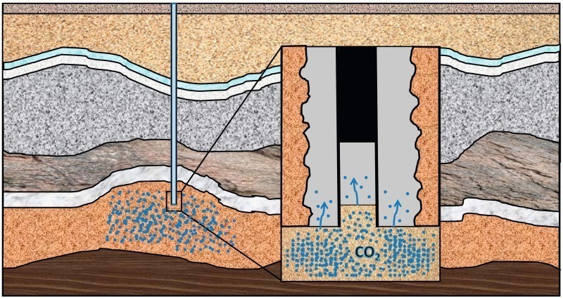
In order to realize the geological storage of CO2, boreholes have to be constructed and lined with cement so that the supercritical carbon dioxide (scCO2) can subsequently be injected into the formation. Typically, such boreholes are sealed with Portland cement [3], which is, however, not CO2-stable [4]. This instability could lead to leaks, through which the CO2 could escape and reach the surface again.
The study here had the objective of modifying conventional oil well cements with additives, in order to increase its CO2 resistance. For this purpose, four cementing systems were selected for different approaches to reduce the gas permeability and these were subjected to conditions of 400 bar pressure with super critical CO2 at a temperature of 90 °C for one and six months. The obtained data would allow conclusions as to whether and how CO2-tolerant Portland cementing systems can be formulated for CCS usage.
2 Materials and storage conditions
Cementing system A was mixed according to a modification (longer mixing times, lower shear rates) of the API specification 10 B-2 [5]. Systems B, C and D were prepared in conformity with rules that were developed by our industrial partners and differ strongly from the API standard. After mixing, the cement slurries were poured into cylindrical plastic containers (h = 50 mm, d = 30 mm) and allowed to set under atmospheric conditions in synthetic reservoir water for two weeks. This synthetic reservoir fluid was intended to simulate the ion content of a depleted oil field in North Germany, which was under consideration as a CO2 storage facility (Table 1).
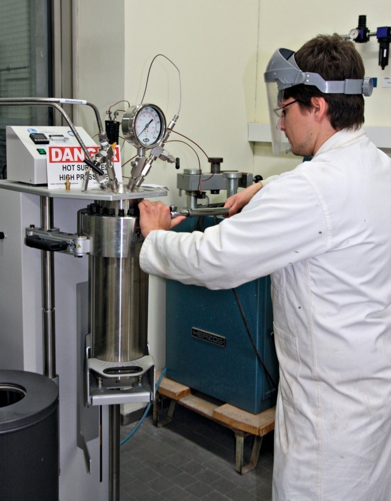
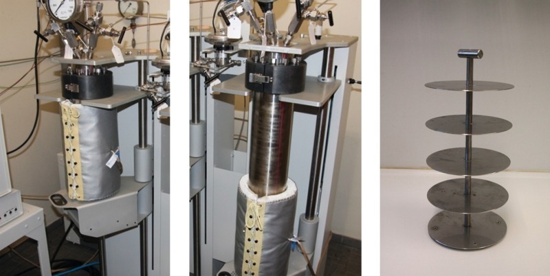
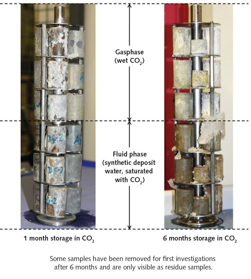
The hardened cement specimens were subsequently removed from the plastic containers and stored for a further 28 days at 90 °C and 400 bar pressure in synthetic reservoir water. This storage took place in 4 L stainless steel autoclaves (Fig. 2) from the Parr Instrument Company (Moline/IL, USA). The samples were subsequently stored in scCO2 in a static manner (without agitation), as this more realistically reflects actual storage conditions in oil and gas strata. For this purpose, 24 test specimens were placed on stainless steel racks, as shown in Figure 3, and these were put into 2 L stainless steel autoclaves (Parr Instrument Company, Moline/IL, USA). The autoclaves were subsequently half filled with synthetic reservoir fluids. Under these conditions, the bottom test samples were exposed to CO2 saturated water (liquid phase) while the top specimens were exposed to a CO2 phase (gas phase) that was saturated with water. The samples were stored for periods of one and six months at a temperature of 90 °C and a pressure of 400 bar. Under these conditions, the CO2 is in a supercritical state and is particularly aggressive to cement. As reference, a second row of test samples of all cementing systems were stored under the same conditions, but in a nitrogen atmosphere instead of CO2.
3 Effect of the scCO2 on the appearance
of the test specimens
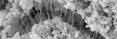
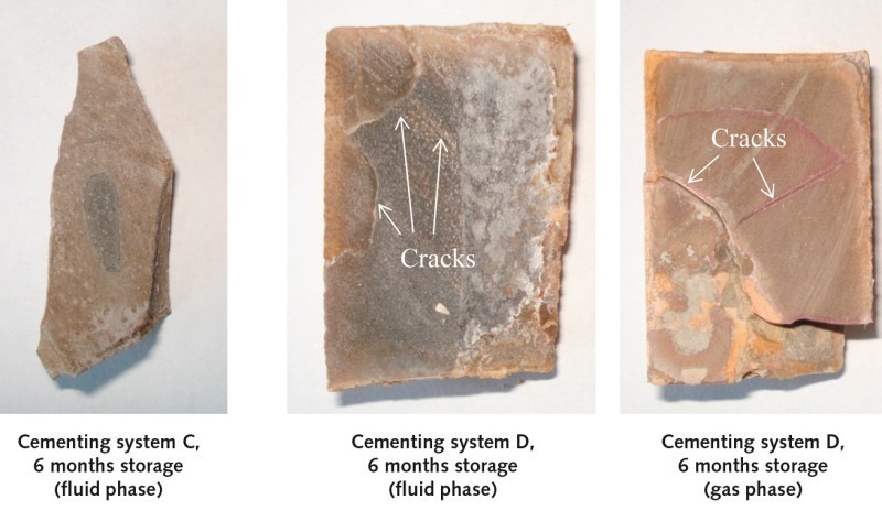
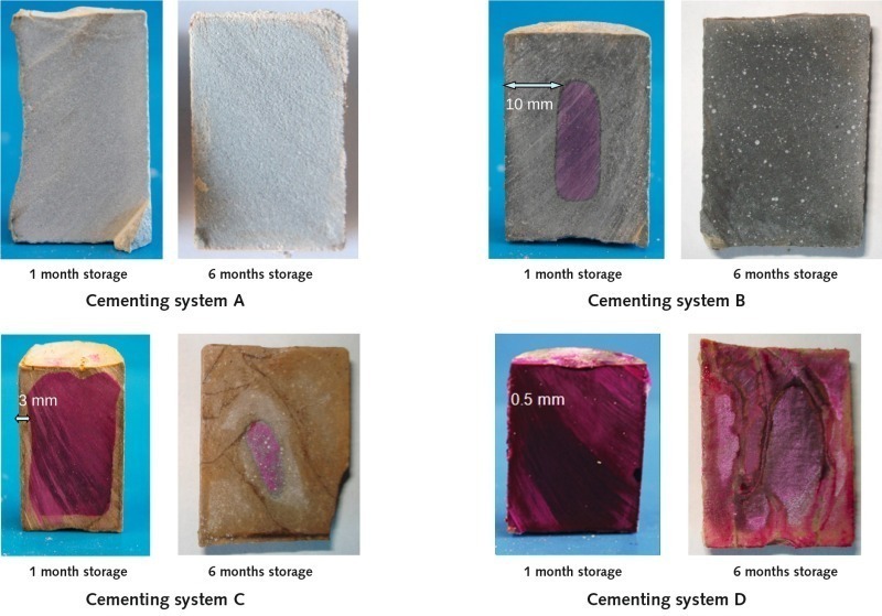
However, the cylinders of cementing systems C and D showed noticeable cracking after six months storage in scCO2 (Fig. 5). The cement matrix of system C samples that had been stored in the liquid phase had been particularly severely attacked by the CO2 and was completely fragmented. The blocks made from reference system D (pure API Class G cement) that had been stored in both the gas and the liquid phase also displayed distinct cracking. However, the cracking was significantly less severe than that of cementing system C.
Cracks in the gas-sealing layer have an extremely negative impact on the storage capability because they provide an immediate escape route through the cement in the direction of the surface. The crack formation is a result of CaCO3 crystallizing occurring in cement. The crystallization of calcium carbonate involves a volume expansion of ~ 11 % [6], which can cause an enormous disjoining pressure within the cementitious matrix.
4 Carbonation of the cement samples
After one month’s storage under scCO2, the various cementing systems showed different CO2 penetration depths. After this short time span, absolutely no alkalinity could be detected in system A, which indicates that these samples were completely carbonated. Due to the relatively low amount of binder in this system, the carbonation appears to progress very rapidly. Cementing system B showed a penetration depth of 10 mm, corresponding to approx. 2/3 of the cylinder radius. The specimens of cementing systems C and D showed only very narrow carbonation zones. These measured approx. 3 mm in system C and approx. 0.5 mm in system D. These results show that the samples of cementing systems C and D suffer far less attack from the scCO2 than do those of systems A and B.
After six months’ storage, the test cylinders of cementing systems A, B and C showed complete carbonation (no alkalinity of the cement matrix). Only cementing system D (pure API Class G cement) retained its alkalinity. However, the system D samples showed considerable cracking, similar to the specimens made of system C cement.
On the basis of the carbonation depth after one month’s storage under scCO2, it is possible to estimate the progression of the CO2 attack over longer periods of time. BARLET-GOUÈDARD et al. postulated a linear relationship between the thickness of the carbonated layer and the square root of the time [7]. Applying this model, the depth of carbonation after a period of 100 years can be calculated. On this basis, the scCO2 would have penetrated to a depth of ~ 35 cm in the test cylinders of cementing system A. In those of cementing systems C and D the depths of the attacked layers would be ~ 11 cm and ~ 2 cm respectively. According to these calculations, the carbonation would progress only very slowly through the different cement samples. At the usual borehole depths of > 2000 m, the cement shells would thus remain gas tight for a period of several thousand years. However, this model does not take into consideration accelerated CO2 ascension due to cracking.
5 Porosity development
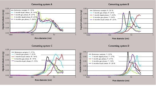
After one month’s storage under CO2, the specimens of system A showed a significant increase in total porosity of 19 vol.-% to 27–34 vol.-% as well as an enlargement of the average pore diameter. This effect can be explained by progressive carbonation of the cement matrix with subsequent washing-out of Ca(HCO3)2. This process had not yet been concluded after one month’s exposure to CO2. After six months’ storage, the number of enlarged pores (diameter of around 80 nm) had further increased in comparison to the one-month storage, while the total porosity remained constant at approx. 26 vol.-%.
In contrast, the CO2 exposure had practically no effect on the total porosity of the cylinders of cementing system B (22–26 vol-%). However, the pore sizes shifted to larger diameters. It is deduced that this is due to progressive erosion of the cement matrix.
The total porosity of the samples made from cementing systems C and D remained very low, even after the exposure to CO2. For the latex polymer-based system C a value of ~ 15 vol.-% was measured and for the non-modified API Class G cement (system D) the porosity varied between 14 and 20 vol.-%. In both cases the pore size had hardly changed.
To summarise, the specimens made from cementing systems A and B showed increased total porosity after storage in CO2, while those of systems C and D retained their low degree of porosity after exposure to CO2. These findings explain why cracking only occurred in the cylinders made from cementing systems C and D, while the matrixes of systems A and B were not damaged. According to the poromechanical model of FABBRI et al., cracking occurs in specimens made of oil well cement particularly if insufficient pore volume is available for the growth of the crystallizing out CaCO3 [8]. It can thus be concluded that cement slurries with a low water to cement value (low capillary porosity), as commonly used in oil well lining, are especially susceptible to cracking. If the cement has a low porosity, the growing CaCO3 crystals do not have enough space to expand and the resultant crystallization pressure fractures the cementitious matrix. The theoretical model of FABBRI et al. has been proven experimentally by the results of the study described here.
6 Permeability development
Acknowledgements
Überschrift Bezahlschranke (EN)
tab ZKG KOMBI EN
This is a trial offer for programming testing only. It does not entitle you to a valid subscription and is intended purely for testing purposes. Please do not follow this process.
This is a trial offer for programming testing only. It does not entitle you to a valid subscription and is intended purely for testing purposes. Please do not follow this process.
tab ZKG KOMBI Study test
This is a trial offer for programming testing only. It does not entitle you to a valid subscription and is intended purely for testing purposes. Please do not follow this process.
This is a trial offer for programming testing only. It does not entitle you to a valid subscription and is intended purely for testing purposes. Please do not follow this process.