Modern engineering of equipment
for the cement industry


The engineering of equipment for the cement industry is in comparison to other industries influenced by some special overall conditions. These are mainly the small built quantities, the very large dimensions of components, the demanded very high availability of plants and the usually unique set of parameters for each and every project. This led to the buildup of expertise using the finite element method (FEM) for computational optimization over the last decades, at least at the reputable equipment suppliers. Until now, this was typically reserved for separate product development due to the necessary effort. Integration into running order executions could usually not or only be poorly realized. This article presents an engineering process that significantly reduces the effort required for computational optimization and thus enables integration into day-to-day business if required. In addition, the presented workflow reduces the effort to dimension project-specifically, whereby the quality can be increased and the possibility is created to offer competitive, individual and tailor-made solutions. The engineering process is based on the consistent use of highly automated 3D CAD models, which form the basis for the 2D production drawings and also the mathematical optimization. A consistent database – one 3D model as the basis for all applications – reduces interface losses.
1 Introduction
Cement plant engineering or large scale plant engineering in general is subject to certain boundary conditions, which influence the equipment engineering for it, make it very challenging and make both the optimization of the engineering processes and the products themselves demanding. From an mechanical engineering view these are:
the small quantities built
the very large dimensions of components
the need for extremely high availability of plants and especially
the constantly changing requirements from order to order, e. g. regarding to plant size, scope of delivery, process...
1 Introduction
Cement plant engineering or large scale plant engineering in general is subject to certain boundary conditions, which influence the equipment engineering for it, make it very challenging and make both the optimization of the engineering processes and the products themselves demanding. From an mechanical engineering view these are:
the small quantities built
the very large dimensions of components
the need for extremely high availability of plants and especially
the constantly changing requirements from order to order, e. g. regarding to plant size, scope of delivery, process engineering, logistics concept, etc.
This means that many projects are unique from an engineering point of view. Of course, in addition to the above-mentioned characteristics, there are a number of universal engineering requirements, namely to design high-quality and safe products as quickly and cost-effectively as possible. As a result, compared to other industries, competences in the field of component analysis have been developed in cement plant construction over a longer period of time and it is possible to fall back on knowledge acquired over decades [1, 2]. To ensure and iteratively improve the theoretical design, measurements have been and are frequently carried out on industrial or experimental plants [3, 4, 5] and the combined methodological competencies are successfully used for product development [6]. The application of these competences typically requires highly specialized knowledge. As a consequence, the use of the capabilities has so far been essentially limited to development projects or product maintenance. In many cases, integration into ongoing order execution has not been possible up to now due to the typical processing times and limited capacities of corresponding specialists. However, in view of the constraints mentioned at the beginning, in particular the small quantities and the unique requirements for almost every order, it would be desirable to use the opportunity with every order to improve the products or to carry them out tailor-made, with the aim of delivering cost-efficiently and with the highest quality. This goal seems reasonable, especially in view of the typical cost structures of many machines, since typically the share of engineering costs in the total costs is low, but a large part of the remaining costs is largely determined by the engineering. In this article an approach is presented, which should make it possible to unite the contradictions mentioned above, i.e. it should allow optimizations and order-specific adjustments to be realized within running contracts. The approach is based on the combined use of modern engineering tools – 3D CAD in combination with FEM - and a high degree of automation of standard tasks, such as the creation of manufacturing drawings.
2 Engineering concept
Order-related adaptation and optimization means choosing the optimum machine size for the respective project and not only using a machine size that fits as well as possible but is already available for this purpose. In addition, this also means dimensioning the machine optimally for the respective load situation if required.
In order to achieve this under the usual deadline pressure, an adapted workflow needs to be established, which reduces the effort for individual dimensioning and optimization in the best possible way. A corresponding workflow is sketched in Figure 1. The core of this is the consistent use of highly automated 3D models with associated manufacturing drawings. These are 3D models that are controlled by the essential characteristic variables of the machine. Dependent sizes and design details are automatically adapted by means of programmed functions. The 2D manufacturing documents required for production are linked to the 3D models, i.e. a change to the basic model leads to an automatic change of the manufacturing information.
A prerequisite for the creation of automated models is a precise and comprehensive design guideline. This guideline needs to define all decision possibilities for the constructive design of the component. This is necessary because otherwise no function relationships to the characteristic parameters of the machine can be defined and programmed. For example, the housing of a clinker cooler is largely defined by its length, width and height. For the automated determination of the required ribbing of the housing, a rule on the required rib spacing is necessary. A well readable minimum example can be found in Figure 2.
A pleasant side-effect of a complete design guideline is that the knowledge gained from experience, which typically grows with each reference, as well as the improvements gained through classical product development can be incorporated directly into the design guideline and thus be applied in general and not only to individual sizes.
The programming represents the practical transfer of the abstract component description into the application. It is noteworthy that this work requires developed programming skills in addition to the classical skills of a design engineer. This means that the implementation is technically demanding and requires a high level of qualification. It should also be noted at this point in the workflow that a high standard of programming quality in terms of documentation, comments and adherence to a uniform programming style (style guide) is required for the sustainability of the working method. Otherwise, there is a risk that programming will become unclear and error-prone. Furthermore, this facilitates maintenance and possible later adaptation of the programming as well as editing in a team.
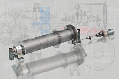
To reduce program complexity, it is advisable to modularize the overall design and to create the programming for individual modules or segments only and then to combine these to form the overall design, see Figure 3. This considerably reduces the number of parameters to be taken into account and thus the number of dependency relationships to be programmed.
As a result of the programming, it is possible to generate a 3D model of the desired machine within a very short time and without detail engineering, using only the essential machine characteristics. The control is typically carried out via tables in which the essential parameters are entered or via a corresponding query via an input mask. From an entrepreneurial point of view, this allows to respond very precisely to project-specific requirements during the offer phase with very little effort and also to be able to respond to change requests that often occur during the project phase. In addition, the methodology supports pricing, since the machine design can be determined very precisely with little effort.
For international manufacturing, which is typical in cement plant engineering, classical 2D manufacturing drawings are still frequently necessary. These are deduced from the 3D models in the presented methodology and linked to the models. This means that as soon as changes are made to the underlying 3D model, they adapt accordingly. A new creation of the production drawings for machine sizes that are not yet available is therefore largely omitted, often only a certain follow-up check of the drawings is necessary.
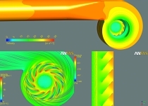
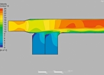
A particular advantage of the approach presented so far is the considerable reduction in the effort required to perform computational component optimization using FEM, see example in Figure 4. Due to the approach presented here, components are available as 3D models anyway, which is the basic prerequisite for corresponding computer simulations. The creation of a 3D model separate from the actual design process only for the purpose of computational optimization is thus completely eliminated. In addition, the parametric design models allow very fast adaptation to the knowledge gained through finite element simulation, which in turn reduces the effort for the often iterative computational optimization. For example, the knowledge that the sheet thickness of a housing was chosen inappropriately can be used quickly for the corresponding adjustment. Thanks to the associated production drawings, there is no need to update them.
In the case of computational optimization, it has proved successful that these are carried out by the design engineer himself and not by a separate computational expert. This applies at least in the case of simpler calculations with a clear path to a solution. Experience has shown that this can significantly improve the understanding of designs and improve the quality of engineering and products. It is advisable to have the possibility of using computational specialists, for technical guidance, for carrying out more complex calculations and for maintaining methodological competence.
It should be noted at this point that finite element simulations are not always necessary. Often highly optimized designs are already available or the potential of a (further) optimization stands in no meaningful relation to the effort, even if it is already very small due to the presented approach.
The significant reduction of the effort to carry out computational product optimizations typically leads to the fact that this is also carried out more frequently and more naturally. This also means that the knowledge about the designs increases. The design guideline essential for the approach presented makes it possible to incorporate this knowledge. This means that optimizations are not only applied in the individual cases analyzed, but can be generalized and thus apply to the entire product range. The presented design process is therefore suitable for continuous, iterative product improvement.
3 Summary
All in all, the engineering approach presented here is a consistent way of working, i.e. a 3D model is used throughout for different applications (the creation of production drawings and the computational optimization). In addition, a high degree of automation is pursued. This minimizes the effort to dimension individually for individual projects and to incorporate optimizations. By using 3D models, the basic prerequisite for computational analyses using FEM is always given, i.e. the effort required is noticeably reduced. This makes it possible to integrate the application of expert knowledge into day-to-day business, which has so far been limited to separate product development, which takes into account the typical conditions in large-scale plant engineering (small quantities, large component dimensions, high quality standards).
//www.thyssenkrupp-industrial-solutions.com" target="_blank" >www.thyssenkrupp-industrial-solutions.com:www.thyssenkrupp-industrial-solutions.com
Überschrift Bezahlschranke (EN)
tab ZKG KOMBI EN
This is a trial offer for programming testing only. It does not entitle you to a valid subscription and is intended purely for testing purposes. Please do not follow this process.
This is a trial offer for programming testing only. It does not entitle you to a valid subscription and is intended purely for testing purposes. Please do not follow this process.
tab ZKG KOMBI Study test
This is a trial offer for programming testing only. It does not entitle you to a valid subscription and is intended purely for testing purposes. Please do not follow this process.
This is a trial offer for programming testing only. It does not entitle you to a valid subscription and is intended purely for testing purposes. Please do not follow this process.