Computational Fluid Dynamics for fans and plants – Part 1


Visit the Special Fans Site at www.zkg.de/fans
Summary: In the field of turbomachinery construction, CFD has, within the space of just a few years, become an indispensable tool for the optimization and new design of turbomachines, as well as for the elimination of fluid-mechanic problems in installed systems. The following paper demonstrates the basic knowledge as well as applied examples of the CFD simulations of process fans.
Computational Fluid Dynamics (CFD) is a method that is used for the computerized calculation of technical flows with state-of-the-art accuracy. With this method, it is possible to make far more precise statements regarding the behaviour of a technical or natural flow than could be made on the basis of classical partly-empirical, test-based approaches. CFD has been employed on an economic scale since around 1973, when it was first applied in the aircraft construction sector. The underlying partial differential equations according to Navier-Stokes, which precisely describe the flow...
Computational Fluid Dynamics (CFD) is a method that is used for the computerized calculation of technical flows with state-of-the-art accuracy. With this method, it is possible to make far more precise statements regarding the behaviour of a technical or natural flow than could be made on the basis of classical partly-empirical, test-based approaches. CFD has been employed on an economic scale since around 1973, when it was first applied in the aircraft construction sector. The underlying partial differential equations according to Navier-Stokes, which precisely describe the flow characteristics of a Newton fluid, have been known since the first half of the 19th century. The calculation work required for solving these differential equations is very complex: the flow volume has to be subdivided into a number of smaller partial volumes that depend on the occurring flow gradients. These partial volumes then form the basis for the equations. For complicated geometries, such as fans, such calculations are therefore only feasible if they are performed by computer. This particularly applies to simulation of transient flow conditions, i.e. conditions that vary over time, as a number of related time steps have to be computed in order to obtain sensible results.
The set of equations describing the processes of momentum, energy and mass transfer is known as the Navier-Stokes equations. These partial differential equations, which were derived in the early 19th century and have no known general analytical solution, can be solved numerically. For the numerical solution of this system of equations, the differential transport equations are first transformed into algebraic equations by so-called discretization. In the case described here, the Finite Volume Method is used for this purpose. This method is generally applied as the basis for simulation programs in the Computational Fluid Dynamics sector. In the FM method, a three-dimensional computational mesh is laid over the flow volume to be investigated. Determination of the distribution of a flow value F thus takes place via discrete calculation points (nodes). In this way, the continuous distribution of F is represented by the F values at discrete points. This creates an algebraic equation (finite difference equation) for every calculation point representing a single computation volume (cell). This algebraic equation is then used for determining the flow values. The differential equations from all the calculation points form a system of linked algebraic equations. This system of equations has to be solved with a numeric algorithm. A number of direct or iterative calculation methods are available for the solution of algebraic equation systems.
As the processing power of available computer technology increases, the application of CFD is becoming more and more interesting for even medium-sized and small companies, in spite of the high purchase and maintenance costs of the software and the present lack of specialist users. One of the biggest advantages of CFD vis à vis classical test bench methods is the ability to examine in detail any desired area within the simulated boundaries and thus to clearly identify and subsequently optimize the zones of rough flow. The field of application of the software thus stretches from the development of new products through the optimization of existing machine series and up to the elimination of fluid-mechanic problems in installed systems. The CFD user gains an understanding of flow phenomena that he can hardly hope to achieve through practical trials, or that can only be obtained at the highest academic level where the limiting factors are then the cost and time involved as well as know-how transfer.
At Venti Oelde the method is not only used for fan construction, but also for system engineering, for instance in the optimization of duct routes, stacks, filter plants, cyclones or the air handling systems of recycling plants. In addition to such tasks as aerodynamic optimization, other fields of application for the software used at Venti Oelde are the simulation of mixing processes in stacks and heat transfers during drying processes and to determine the forces imposed on different structural geometries by the flow passing through them. These can then be employed as boundary conditions for structure-mechanical simulations in order to determine the maximum occurring stresses or for modal analysis to determine possible resonance effects caused by transient forces. In contrast to classical trials, a simulation entails no restrictions with regard to construction size, power consumption, possibly harmful conveying media or high temperatures. To summarize, it can be stated that given the current high technological level of turbomachinery construction, it is practically impossible to make further improvements without the aid of numeric methods, because advancement of machine designs is generally accompanied by an exponential rise in costs compared to benefit.
To allow performance of a CFD simulation a number of work steps have to be carried out in the sequence described below. It is presumed for this purpose that the geometry data and the boundary conditions are known:
a) Creation
The first step is to create a three-dimensional model of the geometry using CAD software with 3D capability. It must be remembered at this stage that in the case of flow simulations the 3D geometry of the flow zone is needed and not that of the structure, as is usual in other types of analysis. Increasingly, the created 3D models are completely parameterized (Figs. 1 and 2) in order to ensure that any modifications in the geometry can be quickly incorporated into the model by simply entering the new dimension, whereupon the entire model and any adjacent zones adapt themselves to the new dimension.
This brings a significant time saving when optimizing the model compared to the otherwise necessary new creation of a different model. In addition, one or more two-dimensional sketches are produced. These can be used for creating three-dimensional models, for example by extrusion, rotation or by means of Boolean operations like cutting or merging.
b) Discretization
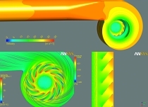
After the required 3D models have been designed, a three-dimensional computational mesh has to be created. The elements of this mesh form the basis for the control volumes that are needed, as already mentioned, for the partial differential equations, so that these can be iteratively solved in matrix form in accordance with the number of elements. Depending on the employed software, the user is generally able to create either a simple-to-generate, unstructured computational mesh (Fig. 3) or a considerably more difficult-to-generate, block-structured mesh (Fig. 4). As a rule, a block-structured mesh with a comparable structure resolution produces better results in significantly shorter processing time.
For this reason CFD studies at Venti Oelde are, with very few exceptions made for time reasons, all based on block-structured computational meshes. Care has to be taken that the flow dynamic boundary layer is given an adequate resolution, because – for instance – flow disruptions are always caused by the boundary layer, as the flow in this zone has to overcome not only the pressure increase but also the wall shear rate. If there is turbulent flow (and nearly all technical flows are turbulent) the boundary layer is only a few tenths of a millimetre thick and has a parabolic curve with respect to the velocity distribution profile (Fig. 5). The computational mesh for this zone must be given such a fine resolution that this parabolic curve is represented with sufficient accuracy. In a normal view of the wall, this requires between 8 and 14 elements in the boundary layer zone (Fig. 6).
c) Simulation
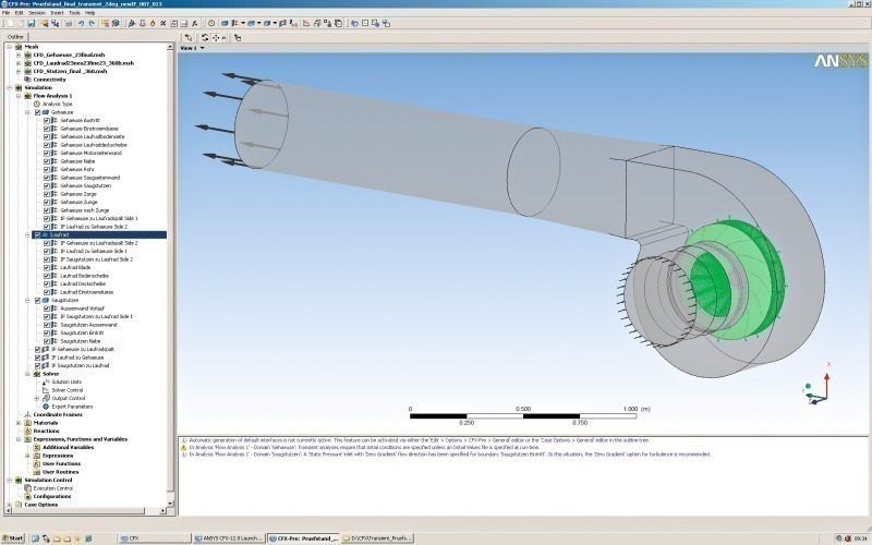
After the 3D model and subsequently the computational mesh have been created, the simulation software (ANSYS CFX) is brought into use. ANSYS CFX consists of three modules: ANSYS CFX-Pre (Fig. 7) for definition of the boundary conditions of the simulation, ANSYS CFX Solver Manager (Fig. 8) for iteratively solving the partial differential equations until a predefined convergence criterion is reached, and ANSYS CFX Post (Fig. 9) for visual and numeric evaluation of the simulation results.
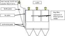
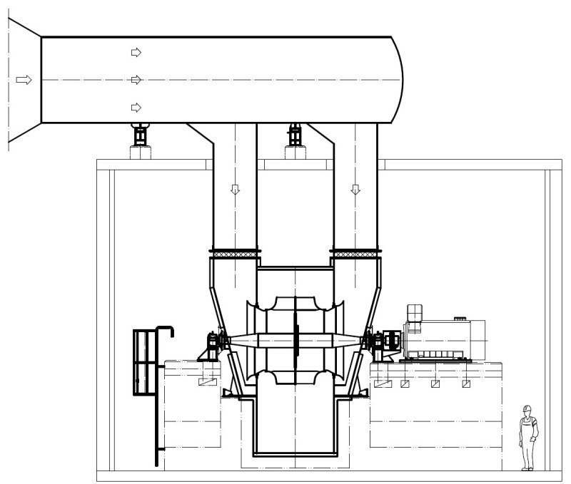
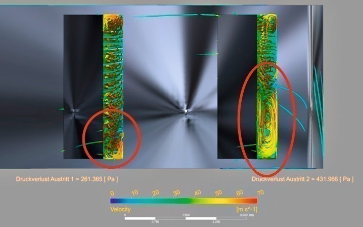
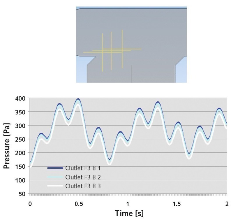
In this case, after modification of a pressure-side duct leading to a stack and containing several branches (Fig. 10), vibrations occurred on one of the fans, causing an automatic safety shutdown. These vibrations had not been experienced prior to the modification. As it could be presumed that the vibration problems were a consequence of non-optimum design of the supply duct, this was analysed in detail by CFD. The stack is around 70 m high while the horizontal duct is approx. 3 m high, 2 m wide and has a total length of approx. 25 m. The mentioned vibration problems affected the fan upstream of the marked duct. It was established that the fan vibrations were caused by poorly designed cross-sections. The measured flow velocity in the horizontal section of the duct was 22 m/s, while that in the vertical section marked in Fig. 10 was only approx. 2‑3 m/s. With approximately comparable duct cross-sections, the flow momentum (mass flow x velocity) of the flow component coming from the left was considerably higher than that entering the collecting duct from below. As can be clearly seen from (Fig. 11), this causes a severe constriction of the air stream entering the collecting duct from the bottom left. As a consequence, there were pressure fluctuations in excess of 250 Pa in this supply duct (Fig. 12), and these throttled the fan so severely that it reacted with significantly increased vibration velocities.
As the described unsatisfactory conditions had to be remedied without significantly interrupting operation or altering the design, it was necessary to eliminate the problem by the simplest means possible. Without altering the duct geometry (Fig. 13), this was achieved by installing two baffle plates (Fig. 14), which accelerated the flow from the two lower supply ducts to the extent that the velocities of all three gas streams are identical at the point where they meet. This measure succeeded in optimizing the velocity distribution (Fig. 15) compared to the original situation (Fig. 11), so that the gas streams meet with identical velocities and no longer negatively affect each other. Also, the pressure fluctuations measured at the points shown in Figures 21 and 25 were reduced from 250 Pa to below 10 Pa. Subsequent to the conversion work, the upstream fan could be run up to its rated speed without any problem. The vibration characteristics were so greatly improved by the conversion work that measurements taken at the fan detected no further effects on fan operation.
Überschrift Bezahlschranke (EN)
tab ZKG KOMBI EN
This is a trial offer for programming testing only. It does not entitle you to a valid subscription and is intended purely for testing purposes. Please do not follow this process.
This is a trial offer for programming testing only. It does not entitle you to a valid subscription and is intended purely for testing purposes. Please do not follow this process.
tab ZKG KOMBI Study test
This is a trial offer for programming testing only. It does not entitle you to a valid subscription and is intended purely for testing purposes. Please do not follow this process.
This is a trial offer for programming testing only. It does not entitle you to a valid subscription and is intended purely for testing purposes. Please do not follow this process.