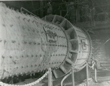
Mechanics of the grinding media in ball mills with longitudinal and transverse motion of the grinding media


This article analyzes the problems of perfecting grinding equipment for large-scale production – cement, ore, coal. An improved design of a ball mill, equipped with internal energy exchange devices, is considered and there is a description of the technical and economic indicators of a standard and an improved mill. The method of calculating the kinematics of motion of grinding media in a mill with longitudinal and transverse motion of the grinding media is described and formulae for determining the effective forces are presented. Equations are given for determining the velocity regimes describing the motion of the grinding media.
1 Introduction
The production of many materials is associated with the need for fine grinding (down to a size of less than 100 µm) of the raw materials: cement, ceramic products, refractories, glass, ferrous and nonferrous metals, fertilizers, coal, etc. [1-3].
About 100 million t of raw materials and clinker are subjected to grinding just in the production of cement and 900 million t in the mining industry [4, 11].
The basic requirements for grinding equipment used in all sectors of the national economy can be formulated from the following general principles: large hourly productivity; lowest...
1 Introduction
The production of many materials is associated with the need for fine grinding (down to a size of less than 100 µm) of the raw materials: cement, ceramic products, refractories, glass, ferrous and nonferrous metals, fertilizers, coal, etc. [1-3].
About 100 million t of raw materials and clinker are subjected to grinding just in the production of cement and 900 million t in the mining industry [4, 11].
The basic requirements for grinding equipment used in all sectors of the national economy can be formulated from the following general principles: large hourly productivity; lowest possible specific electricity consumption; low metal and energy requirement; simplicity in servicing and reliability in operation; the ability to regulate the quality of the finished product and to change to different materials in accordance with their physical and mechanical properties; low capital investment.
The main industrial methods that are widely used in grinding the various materials are: compression, splitting, bending, abrasion and impact [2, 5, 13]. All the known designs of grinding machines are based on these principles. [2-5].
According to Russian and foreign experts, no fundamentally new technological methods of grinding will be created in the foreseeable future. However, complex measures will be implemented to improve the known technology, increase the efficiency and reliability of grinding techniques, and reduce their costs [4, 6, 15].
2 Statement of the problem
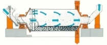
One of the main directions for improving drum mills is the installation of internal energy exchange and classifying devices that ensure the elimination of dead zones in the transverse loading contour by intensifying the motion of the grinding media and carrying out internal classification of the material being ground [7].
A significant drawback of the drum mill is its very low efficiency. Up to 90 % of the energy supplied to the grinding media is consumed by its transformation from electric to thermal energy; in some cases the cement and the exhaust air reach temperatures of 250 °C. This is due primarily to the non-rational interaction of the grinding media with the lining, which is the main link in the transfer of energy from the drive to the grinding media.
It is known that only 45 % of the grinding media participate actively in the grinding process (15 % of these follow free-fall trajectories, while 85 % operate in an abrasion mode), the remaining 55 % move in a dense compact layer in the central region of the transverse loading contour, form dead zones and prevent the material being ground from passing through the mill [8, 9, 12-14]. Experience with the industrial use of the drum mills has shown that the grinding process is organized more efficiently in separator mills, where the finished product is constantly removed from the material being crushed [10, 16]. However, closed-circuit mills are much more complicated in design, which is why they are not widely used in Russia.
A critical analysis of the state and trends in the development of fine grinding technology provides the basis for the following working hypothesis on which the present studies are based - the extremely low efficiency of the ball mill can be significantly improved by rational organization of the operation of the grinding media in each section of the drum while taking account of the selectivity of the grinding process.
3 Analytical studies
When designing models of the motion of the balls and of the entire grinding media, determining the velocities and energy of the impact and calculating the power consumption, the problems are solved using classical formulae – the physical and mechanical properties of the material being ground are not taken into account.
This is for the following reasons. Firstly, the physical and mechanical properties of not just the raw charge but also of each individual particle of the material being ground during the cycle (one revolution of the drum) vary within such wide limits that that is not practically or theoretically expedient to take them into account at this stage in the development of the science. The average size of the pieces of raw material is 30 mm and individual pieces can reach 250-300 mm. The pieces all have various structural defects (cracks, pores, foreign inclusions, etc.) and different shapes so their grindability varies within wide limits (by a factor of 2 or 3).
Secondly, during the passage through the mill of the material being ground (about 30 minutes) the size of a piece of material decreases by a factor of tens of thousands and the strength of individual particles increases by a factor of hundreds. This is because the destruction of the particle occurs due to defects in the structure and as the size of the particle decreases a time will be reached when it does not have any more defects and a great deal of energy is then required to destroy it.
Thirdly, due to the nature of the grinding process, particles of material are found in all the sections of the mill drum with sizes that vary by a factor of thousands and in the first section of the mill by a factor of ten thousand and also have different grindabilities. The charge that is fed into the cement mill includes particles measuring 0.5-200 mm in size.
Fourthly, in-house research and researches by other authors [6, 8] have shown that the presence of grindable material in the ball charge increases the power consumption of the mill drive by no more than 15 %. The existing theoretical models for calculating the power consumption give an error of up to 60 %. This means that, considering the essentially changing physical and mechanical properties of the material being ground, its mass will not only complicate the creation of mathematical models but will also reduce their accuracy. It is therefore considered expedient to consider the mechanics of the grinding media without taking account of the physical and mechanical properties of the material being ground.
Solution of the practical problems of the motion of the grinding media in drum mills is linked with the description of the motion of the outer layer of the ball charge and is described in detail in following works [2, 5, 6, 12]. The trajectory of the ball motion is described by a two-phase model: in the first phase, the ball moves along a circular trajectory together with the drum, the parameters of which are known, and in the second phase the ball travels in free fall through the cross section of the drum along a parabolic trajectory.
In the present work, it is also assumed that if the parameters of the motion of the outer layer of the ball charge are known then it will be possible to calculate all the main energy, design and technological parameters of the drum mill with longitudinal and transverse motion (LTM) of the grinding media with sufficient accuracy for practical calculations.
The additional longitudinal movement of the ball is ensured by the fact that at the moment of detachment the forces acting on the ball include not only the force of the drum pressure but also the longitudinal force from the side of the plane of the partition, ring or lining, inclined to the axis of rotation of the mill drum.
The two-phase motion of a single ball in a fixed coordinate system has been studied in the theory of drum mills and it is assumed that the ball moves along a circular trajectory (until the moment of detachment) together with the drum without slipping and then enters a parabolic free-fall path [2, 6].
A fundamentally new approach is proposed: after the trajectory of the ball has been calculated in a fixed coordinate system, an additional moving coordinate system is introduced that is located in a plane inclined to the longitudinal axis of the mill drum. The effect of the inclined plane with successive changes in its position relative to the fixed coordinate system on the character of the motion of the balls located on the calculated trajectory is then studied, i.e. the study considers not just a single ball but all of them in the whole trajectory of motion.
Calculation of the angle of detachment of the ball located on an inclined plane
In the calculated coordinate system (Figure 1), in addition to the forces considered in the theory of drum mills with LTM of load (force of gravity on the ball, force of inertia, reaction force of the drum), there is an additional reaction force from the inclined plane (IP) acting on a ball located on the inclined plane (inclined partition between chambers, inclined ring, inclined lining ribs, etc.) and coming into contact simultaneously with the inner surface of the mill drum.
On the basis of the accepted calculation scheme, the equation of equilibrium for a ball located on the IP can be represented in the form:
Nn + Nδ + C + G = 0 ⇥(1)
where Nn, Nδ - the respective reaction forces of the IP and the mill drum;
C … centrifugal force
G … weight of the ball
The projection of the unit vectors normal to the partition nn and to the drum nδ at the point A of the position of the ball on the IP can be determined so that Equation (1) can be written in the accepted fixed OXYZ coordinate system (Figure 1).
The projection of the unit vectors normal to the IP:
nnx = cos β sin ξ; nny = –sin β; nnt = cos β cos ξ⇥(2)
The projection of the unit vectors normal to the drum
nδx = sin α; nδy = 0; nδt = –cos α⇥(3)
Using (2), (3) and projecting (1) to the normals nn and nδ gives a system of two equations
Nδ + G cos α – C – Nn cos β cos (α + ξ) = 0⇥
Nn – (Nδ – C) cos β cos (α + ξ) – G cos β cos ξ = 0⇥(4)
This system of equations (4) makes it possible to calculate the reaction of the drum Nδ and IP Nn.
Analysis of equations (4) shows that they can only be solved for positive value of Nδ and Nn. However, when the mill drum rotates the value Nδ and Nn change continuously relative to the
position of the ball on the IP, which is why this system of equations (4) is valid while the ball is moving together with the drum while being located on the IP.
The moment when the ball becomes detached from the inner surface of the drum or IP is characterized by the fact that one of the forces, in the first case Nδ, in the second Nn, disappears, i.e. Nδ = 0, Nn ≠ 0, or Nn = 0, Nδ ≠ 0. In this case, the character of the subsequent motion of the ball depends on which force vanishes first.
For example, if Nδ disappears first, the ball will become detached from the inner surface of the mill drum and continue to move along the IP and the equations (4) describing its motion will take the form
G cos α – C + Nn cos β cos (α + ξ) = 0⇥
Nn + C cos β cos(α + ξ) – G cos β cos ξ = 0 ⇥(5)
The value of the reaction Nn on the ball can be determined from (5) by substituting the value of the centrifugal force in (5).
C = mω2r = mgψ2 ⇥(6)
where m – mass of the ball; g – acceleration due to gravity; ω – angular velocity of rotation of the mill drum; ψ – relative frequency of rotation of the mill drum; r – radius of rotation of the ball.
The appropriate transformations then give
Nn = mg cos β[cosξ – ψ2 cos(α + ξ)]⇥(7)
Analysis of equation (7) forms the basis for the following conclusions: the equation is valid, because at β = 90 ° Nn = 0, i.e. the partition is installed vertically. The trajectory of movement of the grinding media is described by well-known theories; in mills with a smaller angle of inclination of the partition and the rings, grinding media of equal mass move a greater distance along the axis of the drum because at β → <, Nn →>. Grinding media that descend from the IP with larger values of the angle ξ, characterizing the position of the ball on, for example, the IP, will move a shorter distance along the axis of the drum and vice versa, i.e. at ξ →>, Nn →<. With an increase in the relative rotational frequency of the drum the balls also move a shorter distance along the mill drum.
If the reaction from the side of the IP disappears, i.e. Nn = 0, the ball will become detached from it and its further movement can be described within the limits of the known theories.
In this case, equations (5) can be represented in the form
Nδ + G cos α – C = O
(Nδ – C) cos β cos (α + ξ) – G cos β cos ξ = 0⇥(8)
If the ball does not fall on the IP then it becomes detached from the inner surface of the drum at an angle equal to
α = arccos ψ2⇥(9)
The derivation from (8) is confirmed by (9); the ball will detach itself from the inner surface of the mill drum if
Nδ > mg(ψ2–cos α)⇥(10)
The value of the angle of detachment of the ball from the inner surface of the drum is therefore known – (9). It is necessary to calculate the value of the angle of detachment of the ball from the drum when it is in contact with the IP. For this purpose Nδ is determined from (4) with provision for (6). The following expression is obtained after joint solution of equations (4) and (6) and the corresponding transformations:
Nδ = ψ2[cos2 β cos2(α + ξ) –1]
+ cos α – cos2 β cos ξ cos(α + ξ) = 0
Nδ = G ψ2 (cos2 β cos2 (α + ξ) –1) + cos α + cos2 β cos ξ x
x cos(α + ξ)/[cos2 β cos2 (α + β) –1]⇥
⇥(11)
Equation (11) characterizes the position of the ball on the IP when it is in simultaneous contact with the inner surface of the mill drum. It follows from (11) that the detachment of the ball occurs if Nn = 0, i.e. at the moment of detachment from the mill drum its pressure against the ball will obviously be equal to zero.
The equation that characterizes the angle of detachment of the ball from the drum is therefore obtained when Nn = 0.
ψ2 [cos2 β cos2 (α + ξ) –1]
+ cos α – cos2 β cos ξ cos(α + ξ) = 0⇥(12)
Equation (12) takes into account all the main factors affecting the angle of detachment α, the drum rotation frequency ψ, the angle of inclination of the plane β and the position of the IP relative to the ball.
The technique for calculating the angle of detachment is as follows. Equation (12) is solved with respect to α for the given values of ψ, β and ξ. The value of α that has been obtained is then substituted in (7) in which, for the established value of m (mass), the same values of ψ, β, ξ are accepted as for (12). If it turns out that Nn > 0, then the given value of angle α characterizes its detachment from the inner surface of the drum. In this case the ball does not become detached from the IP and does not go into free fall along the parabolic trajectory. Instead, it will move along the surface of the IP because Nn > 0, i. e. the ball is in contactwith the IP. If, when the calculated value of α is substituted in (7), it turns out that Nn < 0 this means that when the ball becomes detached from the inner surface of the drum it does not contact the IP but enters the free-fall trajectory. In this case, the IP does not affect the character of the ball motion, and the angle of its detachment should be calculated from the well-known equation α = arccos ψ2.
Such a situation is possible if
ψ = [cos β cos ξ / cos(α + ξ)]0.5⇥(13)
or
β < arccos ψ2 cos(α + ξ) / cos ξ⇥(14)
Numerical solution of equation (12) therefore makes it possible to obtain each of the functions α (ξ, β, ψ) that have a sinusoidal character. A change in the value of the detachment angle α from a minimum to a maximum for each revolution of the drum clearly causes a change in the operating mode of the grinding media in mills provided with an inclined plane – from a cascade mode to a waterfall mode.
The functions α (ξ, β, ψ) allow the trajectory of the grinding media motion to be characterized under different high-speed operating modes of drum mills equipped with internal energy exchange devices. However, the pattern of the grinding media movement will become clearer if the position of the ball is known at the moment of its detachment from the drum relative to the IP. Additional relative coordinates ox’z’ (Figure 1) have been introduced for this purpose. In the accepted coordinate system, the angle γ determines the position of the center of gravity (CG) of the ball at the moment of its detachment from the mill drum relative to the Z axis.
According to the calculation scheme shown in Figure 1b and 1c the angle γ should be described by the equation
γ (β,α,ξ)⇥(15)
The range covering all possible values is described by the following system of equations
x sin ξ – ytgβ +z cos ξ = 0
x2 + z2 = R2⇥(16)
z = –ctgα · x
The first equation in system (16) is the equation for the inclined plane, the second is for the mill drum with radius R and the third is the equation for the detachment plane determined by the angle of detachment α and passing through the Oy axis.
Simultaneous solution of equations (16) makes it possible to determine the coordinates of the CG of the ball in the stationary system OXYZ at the moment of its detachment:
x0 = –R sin α; y0 = Rctg β cos(α + ξ); z0 = R cos α⇥(17)
If one movable axis z”, which is the projection of the z’ axis on the XOZ plane, i.e.
z” = z’sinβ⇥(18)
is introduced then, in the moving coordinate system, this gives
x0 = R sin(α + ξ); z”0 = R cos(α + ξ)⇥(19)
By taking (18) and (19) into account, the relative coordinates of the position of the ball with respect to the IP can be determined at the moment of detachment from the drum
x’0 = R sin(α + ξ); z’0 = R cos(α + ξ)/sinβ⇥ (20)
Starting from the calculation scheme and using equation (20) gives
tgγ = –x’0/z’0 = sin βtg(α + ξ)⇥(21)
The value of the angle γ can be determined from the expanded form of equation (21)
γ = arctg(sin βtg(α + ξ))⇥ (22)
Some of the results of the numerical solutions of the equations for γ (α, ξ, β) and γ (ψ, β, ξ) are shown in Figure 2.
The functions α, γ (ξ) for (β, ψ) = constant are of the greatest interest. The nature of the dependence α (ξ) that is obtained analytically confirms the conclusion concerning a change in the kinetics of the ball charge. In ordinary drum mills the dependence α (ξ) on the graph is represented by a straight line parallel to the ξ axis. In mills with internal mill energy exchange devices it can be seen from the graphs 1 and 2 (Figure 2) that the angle of detachment during one revolution varies over a wide range. For example, for β = 30 ° and ψ = 0.9, the angle α varies from 15 to 89 °, and for β = 45 ° and ψ = 0.7 it varies from 35 to 80 °. In an ordinary mill the detachment angles are 36 and 60 ° respectively (horizontal sections of curves 2 and 1). From Figure 2 it also follows that with increasing rotational frequency of the drum for all sections of the trajectory, except 60 ° <ξ <105 °, the lifting height of the grinding media increases and its energy increases. This is confirmed by the fact that the function α2 (ξ) has a smaller value than α1 (ξ) (Figure 2). In the phase of the drum movement 0 ° < ξ <55 ° (Figure 2 (2)), the angle of detachment of the grinding media is smaller than in ordinary mills, although it increases from 15 to 36 °. The balls are lifted to a greater height than in ordinary drum mills. At this moment, the grinding media are located at the section of the IP characterized by 7 ° <ξ <105 °, and the radial component of the IP reaction is directed toward the periphery and promotes lifting of the balls (Figure 1).
During further rotation of the mill drum in the 55 ° <ξ <135 ° phase the grinding media become detached at greater angles, i.e. they are lifted to a lower height. The minimum lifting height of the ball also corresponds to a position of the IP for which ξ = 75 ° and is characterized by an angle of detachment equal to α = 89 °. In this case, the coordinates of the ball located on the IP are determined by the angle γ = 172 °. In this section of the trajectory of the ball the radial component of the IP reaction is directed in the opposite direction (toward the centre of the drum) and promotes earlier detachment of the ball. In the rotational phase of the drum, characterized by its rotation from 135 to 322 °, the curve α2 (ξ) has a horizontal section, and the angle of detachment is equal in value to the angle of detachment of the ball in ordinary mills, α = 36 °.
In this case the balls are located to the right of the longitudinal axis of the IP in the range -180 ° <γ <0 ° (Figure 1). It is clear that in this case the IP does not affect the motion of the ball, the reaction is zero. Then, at 322 ° <ξ <360 °, the lifting height of the grinding media increases and the angle decreases to 14 ° (0 ° <γ <7 °). In this case the IP also helps to lift the grinding media.
In one segment that is about a quarter of the drum’s revolution, the grinding media are therefore lifted to a much greater height than in ordinary drum mills and are given greater potential energy, which predetermines the higher efficiency of the grinding process.
The function γ (ξ) clearly shows that the highest altitude of the grinding media corresponds to a mutual arrangement of the ball and the plane for which the point A of the contact of the ball with the IP is in the range 0 ° <γ <105 ° (Figure 2).
This analytical conclusion makes it possible to ensure the maximum height of the grinding along the entire length of the mill drum with a constructive solution based on the relative position of the IP.
4 Conclusions
The following conclusions can be drawn from analysis of the results of calculating the angles of ball detachment for a complete revolution of the mill drum:
for a constant speed of rotation of the drum and a fixed angle of the position of the IP, there are significant fluctuations in the value of the angle of detachment of the ball, which generally changes the mode of operation of the load;
three characteristic areas can be distinguished during the complete cycle of ball motion: the first, where the detachment angles are smaller than in ordinary mills giving a greater height (a quarter of the total revolution); the second, where the balls have a larger detachment angle than in ordinary mills (about 1/8 of the total revolution); the third, where the balls have the same angle of detachment as in ordinary mills (more than half of the revolution);
there is an avalanche detachment of the balls from the drum, when about a third of the balls located in the zone of the IP goes into a free-fall trajectory for a short period of time.
Acknowledgments
This article was prepared within the development programme of the Flagship Regional University on the basis of the Belgorod State Technological University named after V.G. Shukhov, using equipment from the High Technology Center at BSTU named after V.G. Shukhov.
Überschrift Bezahlschranke (EN)
tab ZKG KOMBI EN
This is a trial offer for programming testing only. It does not entitle you to a valid subscription and is intended purely for testing purposes. Please do not follow this process.
This is a trial offer for programming testing only. It does not entitle you to a valid subscription and is intended purely for testing purposes. Please do not follow this process.
tab ZKG KOMBI Study test
This is a trial offer for programming testing only. It does not entitle you to a valid subscription and is intended purely for testing purposes. Please do not follow this process.
This is a trial offer for programming testing only. It does not entitle you to a valid subscription and is intended purely for testing purposes. Please do not follow this process.