Extraction characteristics of bulk materials from silos
Part 1: Basic experimental and theoretical principles

Summary: As part of this work experimental investigations were carried out with a rectangular silo. The main focus was on the stress states during emptying by two silo extraction screws and the relationships between the wall normal stresses, the flow profiles and the torques required for the extraction screws. Among other things it was established that the wall normal stresses are lower in moving zones than in stationary zones. The findings and relationships that were discovered can be reliably applied to industrial plants. Part 1 of the article deals with the basic experimental and theoretical principles and Part 2 deals with the test results.
1 Introduction
Silos have been used for centuries for storing bulk materials. It is important not only that the required quantity of bulk material can be stored in a silo but also that it can be emptied out of the silo at the required moment. The way the silo is emptied can, depending on the nature of the bulk material, play a central role. Furthermore, mass flow is usually the required flow profile, especially if the bulk material is sensitive to ageing or tends to consolidate with time. Mass flow is understood as the state in which the entire contents of the silo are in motion during the...
1 Introduction
Silos have been used for centuries for storing bulk materials. It is important not only that the required quantity of bulk material can be stored in a silo but also that it can be emptied out of the silo at the required moment. The way the silo is emptied can, depending on the nature of the bulk material, play a central role. Furthermore, mass flow is usually the required flow profile, especially if the bulk material is sensitive to ageing or tends to consolidate with time. Mass flow is understood as the state in which the entire contents of the silo are in motion during the emptying and there are no dead zones. Process engineering silo design is necessary to ensure trouble-free emptying of a bulk material from a silo and is now state of the art. The optimum silo geometry for achieving mass flow is determined by taking into account the bulk material properties. The stresses that occur in the bulk material are of central importance in the silo design. Ever since Janssen [1], i.e. over a hundred years ago, people have been concerned with these stresses in silos. Janssen examined the stresses in a silo shaft in 1895. This was followed later by numerous works that considered the stress distribution in the cone. The best known are the works by Jenike [2–3] and Schwedes [4]. The method of calculation employed by Jenike, the so-called Jenike method, now forms a central element in the process engineering design of a silo.
It often happens in practice that the silo geometry determined during the silo design cannot be implemented because, for example, of structural factors in an existing building or for cost reasons. It is often necessary to use an existing silo for a different bulk material. If process engineering problems are expected for a silo during extraction of the bulk material then suitable measures have to be taken that will have a beneficial effect on the bulk material flow in the silo. Extraction units are normally used. In addition to their main task of extracting the bulk material they also assist or stimulate the bulk material flow in and out of a silo. During this process the extraction units should ensure controlled and possibly also metered removal of the bulk material. The extraction units often used in practice are belt conveyors, apron conveyors, troughed chain conveyors, vibrating troughs, rotary-vane feeders and screw conveyors. With the exception of rotary-vane feeders these extraction units are, in principle, also suitable for extracting bulk materials from a rectangular, oblong, silo. A characteristic of belt conveyors, apron conveyors and troughed chain conveyors is that they are linear conveyors. This means that the belt, slat cell or chain moves linearly relative to the silo over the entire outlet opening in the direction of discharge. Uniform extraction of the bulk material over the entire outlet cross-section can only be ensured to a limited extent and requires adaptation of the silo geometry [5]. Not only are screw conveyors simple, inexpensive and enclosed units but they also have the advantage when used as silo extraction screws that the extraction of the bulk material is achieved by rotation. In contrast to linear conveyors, in which a section of belt, a chain segment with flights or a slat cell passes through the entire outlet opening from back to front, the screw flights or segments always remain within the outlet opening in the same position relative to the direction of conveying. This means that the screw geometry can be optimally adjusted so that theoretically the extraction of bulk material takes place over the entire outlet opening.
It is accepted that different stresses occur in regions of the bulk material that are flowing at different velocities [4–8]. If an extraction unit withdraws bulk material unevenly then it follows that this will generate regions with different velocities, and therefore different stresses. Even with uniform bulk material extraction higher stresses will occur at the forward extraction end face when using an extraction unit such as silo extraction screws because of the bulk material friction. So far these increased stresses caused by the extraction unit have not been either quantitatively or qualitatively investigated. However, an understanding of this increased stressing can be of significant importance if the intention is to store and extract bulk materials that tend to consolidate. Even if the silo geometry means that only small stresses would occur at the outlet it is sometimes possible for critical increases in stress to be generated and exceeded by the extraction unit and cause excessive consolidation or flow problems in the bulk material. The extraction unit and the silo affect one another and are dependent on each other. Firstly, the extraction unit influences the bulk material flow and the stresses that occur in the silo and, secondly, the stresses in the silo in turn affect the extraction unit, e. g. with
respect to the requisite drive rating. This publication indicates the relationships between the normal wall stresses that occur and the extraction characteristics of silo extraction screws in a silo. 2 Basic principles
Figure 1 provides a clear illustration of the different pressure and stress distribution curves for bulk materials and liquids – in a container filled with liquid the liquid forms a horizontal surface (Fig. 1a). The liquid pressure increases linearly, and hence hydrostatically, with increasing depth (Fig. 1c). In a container filled with bulk material a cone of bulk material is formed, assuming central filling (Fig. 1b). This is because a bulk material can transmit shear stresses even when at rest. With increasing depth the container wall takes part of the weight of the column of bulk material. Consequently, with increasing depth the pressure in a bulk material rapidly approaches a maximum and limiting value.
The most frequent problems encountered when bulk materials are stored and flow in a silo are bridging, rat-holing and segregation (Fig. 2). With bridging the bulk material forms a stable arch above the outlet opening that prevents any further discharge of the material (Fig. 2a). With rat-holing the only material that flows out is the bulk material directly above the outlet. This results in a vertical shaft (Fig. 2b). Segregation by particle size, particle shape or particle density can occur when a silo is being filled (Fig. 2c). This is most serious with bulk materials with a wide particle size distribution. With central filling the larger particles collect at the perimeter and the fines collect in the centre. When the flow profile is examined a distinction is made between mass flow and funnel flow (Fig. 3) [2–6, 8–9]. The aim is usually to achieve mass flow because all the material in the silo moves during the discharge, while dead zones are formed with funnel flow. These dead zones are regions in which the bulk material is stationary at first (Fig. 3b) and only moves during complete emptying. Very wide residence time distributions occur in funnel flow silos because of the dead zones.
A stress distribution curve of the type shown in Figure 4 is formed after an empty silo has been filled. This stress state (Fig. 4a) is also designated an active stress state or filling state. The stress in the silo shaft increases in the downward direction with increasing distance from the surface of the bulk material and tends towards a maximum value. The transition to the cone causes a point of discontinuity for the wall normal stress w. The stress in the cone may rise further or decrease depending on the geometry. A striking feature of the filling state is that the greatest principal stress 1 at the silo axis points vertically downwards. The curves shown are trajectories of the greatest principal stress 1.
As soon as the bulk material starts to be extracted from the silo the active stress state in the cone changes abruptly to the passive stress state, starting from the outlet (Fig. 4b). Starting from the tip of the cone the radial stress field in the convergent cone spreads upwards as far as the transition to the vertical silo shaft (Fig. 4c). The active stress field is retained in the vertical silo shaft even while the bulk material is being extracted. If the extraction of bulk material is interrupted then the entire stress state is retained just as it is.
A characteristic of the passive stress field is that the trajectories of the greatest principal stress 1 run horizontally at the silo axis. The “switch” forms at the transition from passive to active stress field and designates the stress peak that marks the point of transition from the active to the passive stress field (Fig. 4 b–d). The stress peaks are a consequence of the equilibrium of forces between the weight of the entire filling of bulk material and the vertical components of the wall normal stresses and wall shear stresses [5]. If dead zones (funnel flow) are formed in a silo during the extraction (Fig. 4d), then a stress peak also occurs at the point at which the dead zone meets the silo wall. This is because, as with a cone, a convergent flow of bulk material is formed inside the dead zone. The boundary line between rest (dead zone) and movement cannot be determined analytically so the precise positions of the stress peaks in a funnel flow silo are not known in advance. This means that possible stress peaks in the entire silo shaft must be taken into account during the static dimensioning of the silo walls.
A large number of different extraction devices are available for extracting bulk materials from a silo [5–6, 9–16]. The extraction devices must always be correctly dimensioned for the case of the greatest loading, i.e. for when the greatest vertical stress occurs. As already explained above, the vertical stress in the filling state (active stress state) is greater than in the emptying state (passive stress state). An extraction device therefore has to apply the relatively greatest extraction force when first extracting bulk material after an empty silo has been filled. After the passive stress state has become established in the cone the vertical stress drops, so the force required for further extraction of the bulk material also drops. These relationships are shown in Figure 5. According to information from Schwedes and Schulze [6] and according to measurements by Schulze [5] the vertical stress in the filling state can amount to five- to ten-times the vertical stress in the emptying state. If the bulk material flows off-centre or asymmetrically from a silo then this is termed eccentric emptying [6]. Eccentric emptying means principally an uneven stress distribution around the perimeter. It is imperative that this is taken into account when dimensioning the silo for strength. Numerous cases of damage to silos are known in practice that can be attributed, among other things, to eccentric emptying and the associated uneven and therefore locally higher loading in a silo [17].
3 Test set-up
The following aspects of the extraction characteristics of different silo extraction screws were examined during the investigations that were carried out:
– resulting flow profiles
– resulting wall normal stresses
– requisite drive rating
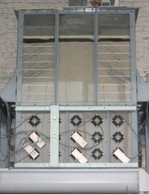
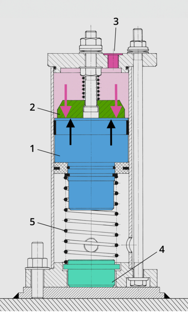
The set-up of the test plant used is shown in Figure 6. The plant consists of a prism-shaped test silo (1), the extraction system (2) and two screw conveyors (3) and (4), which transport the bulk materials back into the test silo in a closed circuit. Flexible connections were installed before the test silo and after the extraction system to avoid excessive vibrations or any detrimental effects on the measurements in the test silo. These flexible connections isolated the test silo and the extraction system from the rest of the plant. The general structure of the test silo can be seen in Figure 7. The lower part of the silo was fitted with stress-measuring cells [18–19] on all four silo walls. The arrangement meant that the wall normal stresses could be measured in three planes so that the stress distribution could be measured both in three horizontal planes and also in several vertical planes.
The extraction system used consisted of two silo extraction screws that were arranged parallel to each other at the base of the test silo and were loaded with bulk material over the entire length and width of the silo. Because of the characteristic features of extraction screws with respect to their extraction and intake behaviour the screw geometry for the investigations was as follows:
The external diameter D was kept constant to ensure fundamental activation of the entire silo base and to avoid dead zones caused solely by the design. The shaft diameter d was also kept constant. The screw geometries shown in Figure 8 were chosen in principle in order to be able to determine and compare the different extraction characteristics. Extraction only from the rear area would be expected with the screw geometry S1 with constant pitch, while the chosen screw geometry S2, characterized by a graduated progression, should achieve uniform extraction over the entire length of the silo.
The test series shown in Table 1 were used for the investigations. For the listed screw pairing the left-hand extraction screw (seen in the direction of transport) is shown in the first column and the right-hand extraction screw in the second column. The bulk material used for the test was free-flowing, furnace-dried, quartz sand. The quartz sand used was non-cohensive and had a bulk density that was virtually independent of the stress. The effective angle of friction e was determined with a ring shear apparatus as described by Schulze [20], and the angle of wall friction w was measured with a shear apparatus as described by Jenike. Plexiglas was used as the wall material for the silo walls. The average particle size d50 (median value of the Q3 distribution) was determined with the aid of a sieve analysis (Fig. 9). The horizontal load ratio was measured in a lambda meter [19]. A constant horizontal load ratio was measured when the vertical stress v was varied from 5 to 78 kPa. The bulk material properties are summarized in Table 2.
Überschrift Bezahlschranke (EN)
tab ZKG KOMBI EN
This is a trial offer for programming testing only. It does not entitle you to a valid subscription and is intended purely for testing purposes. Please do not follow this process.
This is a trial offer for programming testing only. It does not entitle you to a valid subscription and is intended purely for testing purposes. Please do not follow this process.
tab ZKG KOMBI Study test
This is a trial offer for programming testing only. It does not entitle you to a valid subscription and is intended purely for testing purposes. Please do not follow this process.
This is a trial offer for programming testing only. It does not entitle you to a valid subscription and is intended purely for testing purposes. Please do not follow this process.