Cracks in silo walls
Is it a must to repair and strengthen or even demolish silos if wide cracks are observed? This question might be best answered by means of an example of a reinforced multi-chamber raw meal silo. In this article a special case will be highlighted which may be of interest for many cement producers.
1 Introduction
In general silos are structurally delicate structures. They consist of shell elements and can carry membrane tension or compression forces very well. However any bending moments or shear forces could lead to problems to the structural stability of the silo. In the given case the owner determined several extremely wide cracks in his unconventional multi-chamber raw meal silo during the regular inspection. A first expert opinion came with the result that the silo is under designed and must be strengthened with a heavy steel construction to regain structural stability. As the...
1 Introduction
In general silos are structurally delicate structures. They consist of shell elements and can carry membrane tension or compression forces very well. However any bending moments or shear forces could lead to problems to the structural stability of the silo. In the given case the owner determined several extremely wide cracks in his unconventional multi-chamber raw meal silo during the regular inspection. A first expert opinion came with the result that the silo is under designed and must be strengthened with a heavy steel construction to regain structural stability. As the proposed strengthening work seems to be quite expensive and would mean a long interruption of the operation, the owner decided to obtain a second expert opinion.
The owner commissioned Scherr+Klimke, an experienced architectural and engineering society of Neu-Ulm, Germany to review the proposed strengthening solution. After a quick review of the provided documents they had to answer the following main questions:
How is it possible to have an overstress in the silo by the new structural analysis done by first expert of more than four or even locally eight times and the silo is still standing.
If the silo has so many wide cracks, wouldn’t it be better to build a new silo and demolish the existing one, instead of strengthening the existing silo at about 70 % of the cost of building a new one.
The silo owner was convinced to give Scherr+Klimke two to three weeks time for a more comprehensive analysis. They started by analyzing the facts and made a new structural analysis with the following outcome:
There’s no need for any strengthening work for the time being.
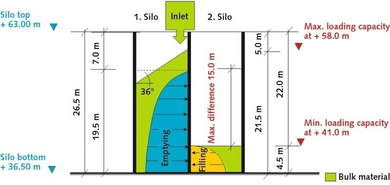
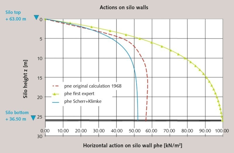
Some constrains for operation were given, such as having a maximum filling degree difference between the neighboring silo cell of 15 m, reducing the outlet injection air pressure from 0.8 to 0.5 bar and reducing the filling capacity 7 m lower than designed (Fig. 1).
A monitoring system will be installed to measure the real stress condition of the silo during operation for a one year period to take all weathering seasonal effects into consideration.
The costs of the monitoring system were hardly about 5 % of the cost of the proposed strengthening. Furthermore, the operation could continue without any disturbance. In order to come to the above given conclusion, several structural investigations had to be made as follows:
2 Silo key data
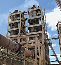
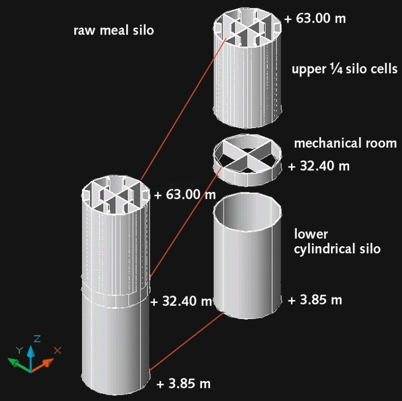
The given raw meal silo was built in 1968 of reinforced concrete without pre-stressing and consists of three main parts (Fig. 2):
Upper part 4 x ¼ silo cells
Middle part mechanical equipment room
Lower part mixing cylindrical silo
The upper four-chamber silo is divided by two main reinforced concrete cross-walls into four cells. The lower part has a cylindrical shape and is hinged to the solid foundation. The silo has a diameter of about 18 m and a total height of 63 m.
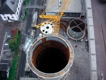
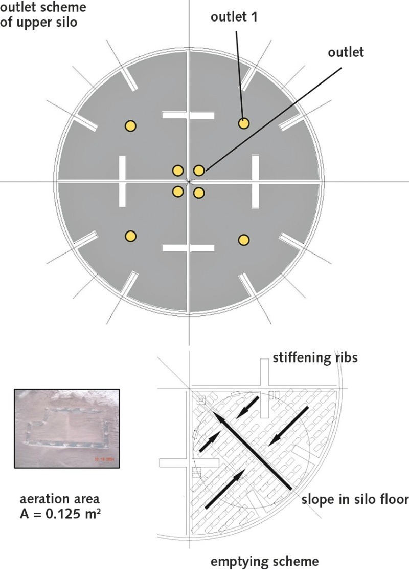
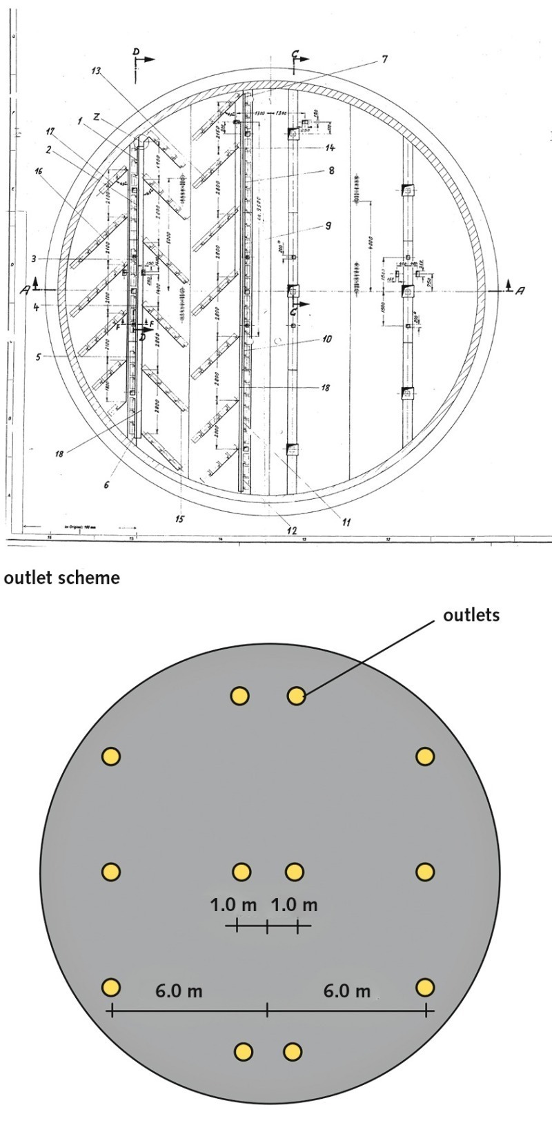
The outlet of the upper silo part is shown in Figure 3. The pneumatic extraction is achieved over two openings at the same time for each ¼ silo cell. Hence the extraction of upper ¼ silo cells is defined as eccentric emptying from the structural point of view. The extraction of the lower silo cylindrical part is homogeneous over all 12 extraction openings as shown in Figure 4. Hence the extraction of the lower silo part is defined as non-eccentric emptying from the structural point of view.
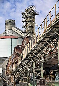
3 Site assessment
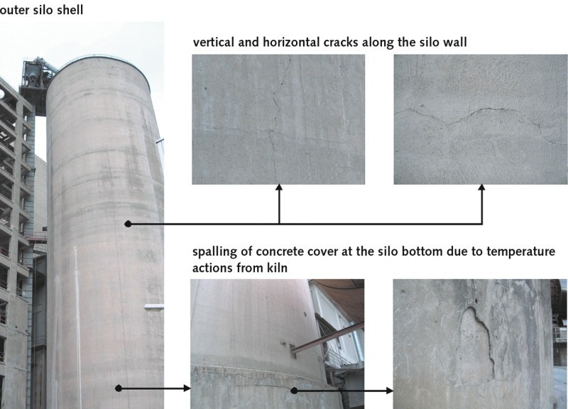
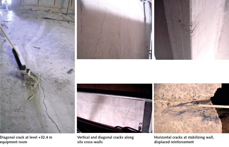
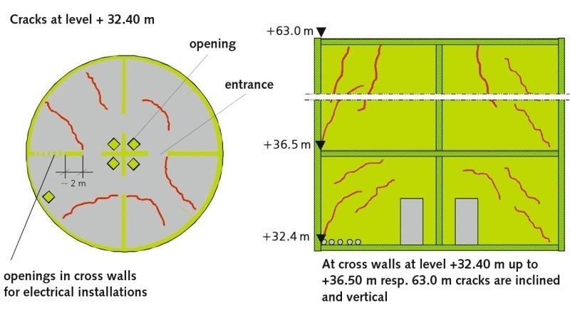
A site assessment was done to evaluate the structural condition of the silo and to monitor the cracks schematically. The inspection was done from the outside and from the inside of the silo during the regular maintenance period of the plant. Some of the main damage from the outside such as cracks and spalling of the concrete cover are shown in Figure 5. Further wide cracks in slabs and walls of mechanical resp. equipment room at level +32.40 m to +36.50 m can be seen in Figure 6. For a better overview the structurally relevant cracks are shown schematically in Figure 7.
4 Structural analysis
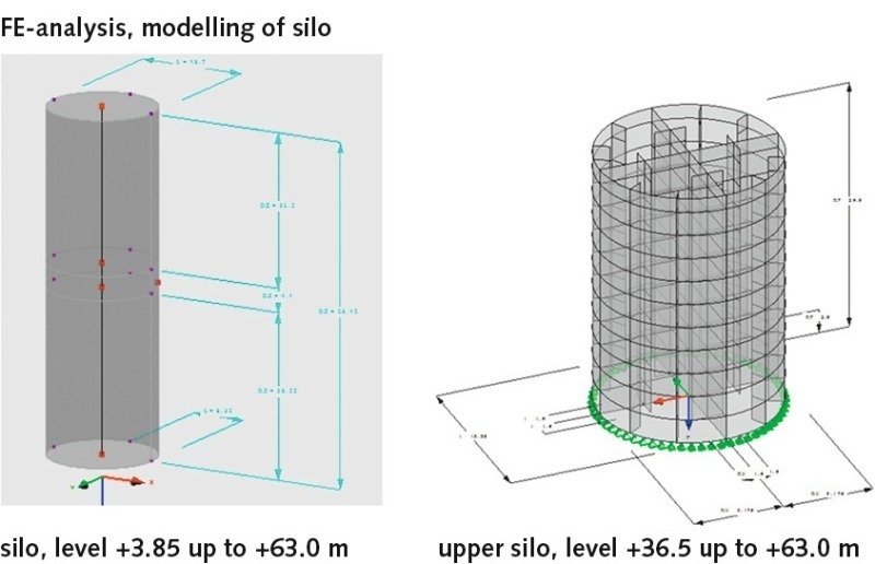
A structural analysis with the finite element method was made to investigate the structurally critical areas of the silo. As the silo geometry and shape especially for the upper 4 x ¼ silo is not covered by the present silo design code some assumptions and adjustments of the main parameters for the structural analysis had to be taken compared with the original calculation note.
The main parameters were adjusted and assumed as follows:
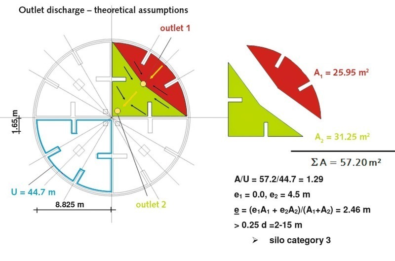
The U/A value which means circumference to area ratio and the corresponding eccentricity of outlet were determined as given in Figure 8.
The design values for bulk material parameters such as bulk density, angle of internal friction etc. were assumed as given in Table 1.
From the above assumptions the pressure and actions on the silo were determined as exemplary shown for the unconventional upper 4 x ¼ silo in Figure 9. It is clearly seen that the load assumption of the first expert was far too high compared with the original structural analysis of 1968. That was one of the reasons why the first expert opinion showed an overstress of more than 4-times the allowable stresses.
With the finite elements method (FE-method) the location of maximum stresses in each silo cell were determined in order to find out the locations of measuring devices.
A measuring concept was then developed accordingly.
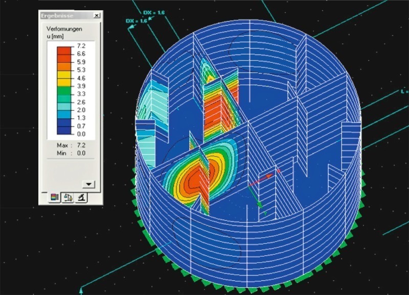
The finite element model of the whole raw meal silo and the details of the upper 4 x ¼ silo are shown in Figure 10. As expected the maximum deformations resp. maximum stresses were located at the mid-height of the cross-walls of the upper 4 x ¼ silo (Fig. 11). On the other hand it was found out that the additional vertical walls connected to the outer silo wall in radial direction have only medium stress level.
5 Monitoring system
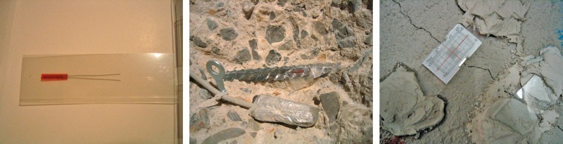
Based on the outcome of structural analysis and site assessment a monitoring concept was developed. Mainly three measuring devices were installed along the height of the whole silo and inside the intermediate mechanical room as shown in Figure 12:
Ordinary crack gauges measuring the crack width development
Strain gauges directly fixed on the concrete surface over the cracks to measure the concrete stain
Strain gauges installed at the existing main reinforcement at the location of the cracks to measure the strain in the rebar at crack to detect maximum stresses.
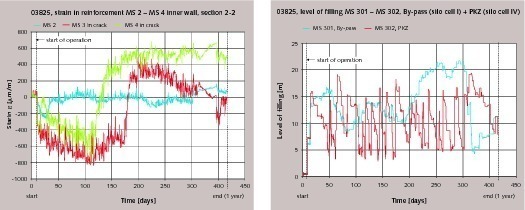
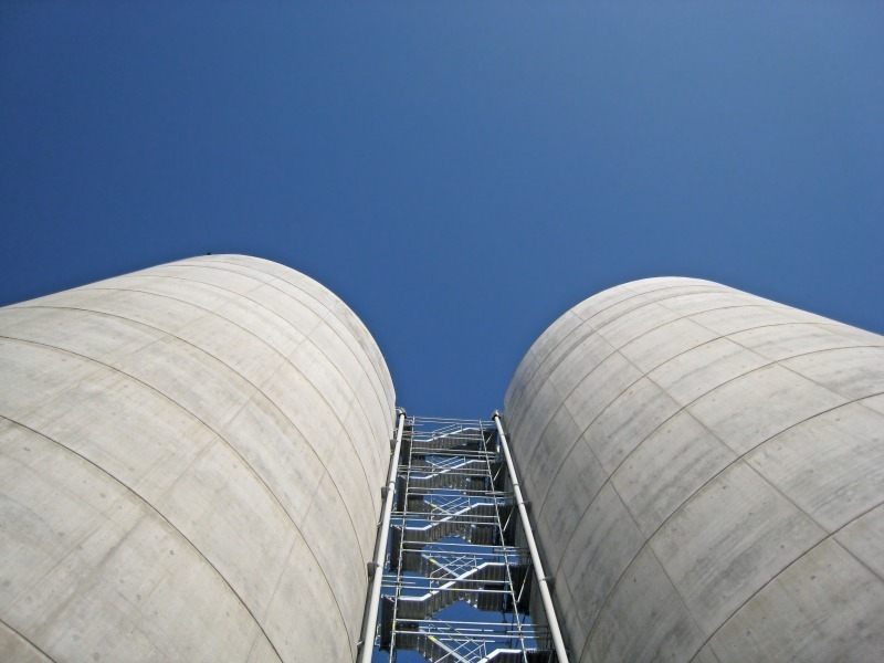
The strain due to temperature action was neutralized by dummy strain gauges installed at reinforcement bars. After checking the measuring system a reference measurement was done before starting normal operation of the silo. The silo operation started as planned besides the stress monitoring. All measuring data were transferred continuously and automatically via a mobile network. Having the data about the filling degree the stain at the main reinforcement could be monitored to be below the allowable design limits as exemplary shown in Figures 13a and 13b.
6 Final outcome
The outcome of monitoring the silo over one year confirmed the assumptions and results of structural analysis. Based on the fact that the initial constraints were adjusted in favor of the operation as follows:
No need for any strengthening work for the time being
Minor repair work should be done e.g. due to spalling of the concrete cover due to temperature action close to the kiln.
Regular inspection of the silo must be carried out by an expert in order to detect any changes in the cracks.
Air injection pressure is reduced from 0.8 to 0.5 bar
The max difference between the filling levels of neighbouring silo cells is limited to 10 m
The filling capacity of the upper 4 x ¼ silo is limited to 90 % which is 3.0 m lower filling height than designed
The monitoring can be stopped. However if any changes in crack pattern are observed monitoring can be reactivated in an easy manner as all measuring devices are permanently installed.
7 Summary
It is shown that it is not always recommended to repair and strengthen or even demolish concrete silos if wide cracks are detected. An engineering study of the given situation should be carried out taking the option of monitoring into account. A suitable monitoring system could lead to effective final solutions and cost savings.
Überschrift Bezahlschranke (EN)
tab ZKG KOMBI EN
This is a trial offer for programming testing only. It does not entitle you to a valid subscription and is intended purely for testing purposes. Please do not follow this process.
This is a trial offer for programming testing only. It does not entitle you to a valid subscription and is intended purely for testing purposes. Please do not follow this process.
tab ZKG KOMBI Study test
This is a trial offer for programming testing only. It does not entitle you to a valid subscription and is intended purely for testing purposes. Please do not follow this process.
This is a trial offer for programming testing only. It does not entitle you to a valid subscription and is intended purely for testing purposes. Please do not follow this process.