Safety nets protect workers in preheaters
Safety nets make it possible to safely arrest falling debris and assure the safety of the employees working below. An important aspect is the fact that the brakes must be mounted on the exterior of the riser duct. The safety net is also installed in the riser duct from outside. Dyckerhoff is now equipping all its clinker plants with such nets, in view of the extremely good experience gained up to now and the high safety level achieved for employees working in the kiln inlet chamber and riser duct.
1 Introduction
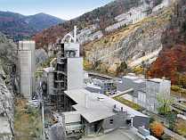
In modern kiln installations, the riser ducts and calciners take the form of large masonry-lined plant sections of great structural height. Employees must be protected against falling encrustations and refractory material when repairs are being made in the kiln inlet chamber and the preheater.
The following safety precautions are customary in the cement industry before work is performed in preheaters:
Visual inspection of the masonry by experienced colleagues for condition and encrustations
Removal of encrustations in the riser duct from the inside by industrial climbers or from...
1 Introduction
In modern kiln installations, the riser ducts and calciners take the form of large masonry-lined plant sections of great structural height. Employees must be protected against falling encrustations and refractory material when repairs are being made in the kiln inlet chamber and the preheater.
The following safety precautions are customary in the cement industry before work is performed in preheaters:
Visual inspection of the masonry by experienced colleagues for condition and encrustations
Removal of encrustations in the riser duct from the inside by industrial climbers or from the outside
Installation of safety scaffolding at multiple levels to protect against falling lumps of masonry and encrustation
The safety scaffolding used consists of steel or aluminium beams, scaffolding tubes and square-section timbers with scaffolding boards positioned on them. Several working platforms are frequently installed one above the other, in order to limit potential fall heights.
One of the major drawbacks of this procedure is the fact that employees have to enter the danger zone for inspection and clearance purposes without protection, and to install the safety scaffolding.
Visual inspection cannot provide total safety, however, since dangerous encrustations are not always visible and corroded lining anchors are almost never easily recognisable.
2 Initial situation and assignment
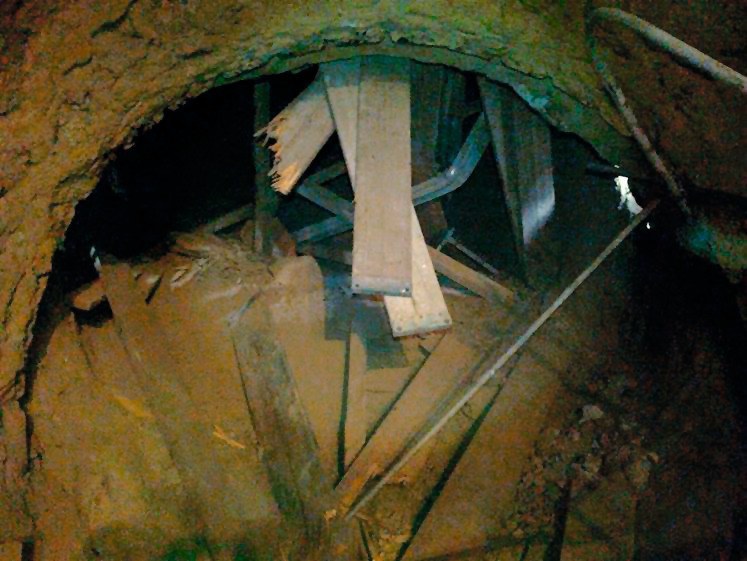
In one incident in a riser duct, an approx. 300 kg lump of encrustation detached and fell through the safety scaffolding. The scaffolding beams were buckled like matchwood (Figure 1).
A specialist institute was then commissioned for the structure-analytical design of a platform structure which would be capable of stopping a 1 t lump of encrustation/shotcrete/masonry falling from up to 10 m. The most diverse range of computations and simulations was performed for this purpose. These indicated that such a lump accelerates to approx. 15 m/s while falling and impacts onto the safety scaffolding with a force of 580 kN.
No rigid platform structure is capable of stopping such a lump of debris. This can be achieved only by using resilient structural elements.
3 Solution after feasibility study by Geobrugg
The search for suitable employee protection which would reliably stop a 1000 kg lump of debris falling from a height of 10 m involved the testing of nets similar to those used to prevent rockfalls in the Alps.
The Swiss company Geobrugg was commissioned to perform a feasibility study on the use of safety nets in riser ducts. Nets suitable for this application include ring nets and nets consisting of high-tensile steel rods. The net must be folded very small to permit its entry into the riser duct via a hatch. It is then opened in the riser duct by pulling at its corners. All the necessary work has to be performed from outside.
Two types of brakes were tested for the absorption of the kinetic energy of the lump of encrustation, which the net itself cannot absorb:
Spring brakes
Bar brakes
In the case of the spring brake, a high-alloy steel spiral is extended (stretched) when a load is applied. The energy is “consumed” in the steel by the act of deformation.
The design computations indicated that the net would need to have up to sixteen spring brakes to be able to safely absorb the energy generated. It would not be possible to install so many spring brakes, however, due to the space available on such riser ducts. Spring brakes are therefore not suitable for this application.
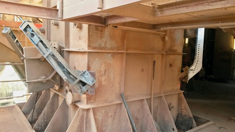
In bar brakes, a long bar of flat steel is forced around a journal or a roller when load is applied, and the energy is absorbed by the deformation of the steel bar. Geobrugg developed for this purpose an innovative bar brake which can be used as a standard on all Dyckerhoff riser ducts. The new brake can absorb so much energy that only one brake at each corner is needed, even on the largest riser duct cross-sections (Figure 2).
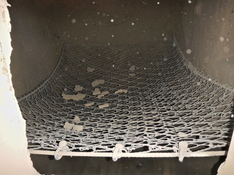
The octagonal arrangement of the holes in the flange permits variable fitting of the brake to the riser duct at 45° intervals. Geobrugg has developed a multi-mesh safety net for this riser-duct application (lead picture). A thick plastic film to capture trickling material is “sandwiched” between the two meshes, and also prevents them from snagging into each other.
The safety net and the brakes have been designed for a safety factor of > 2.6.
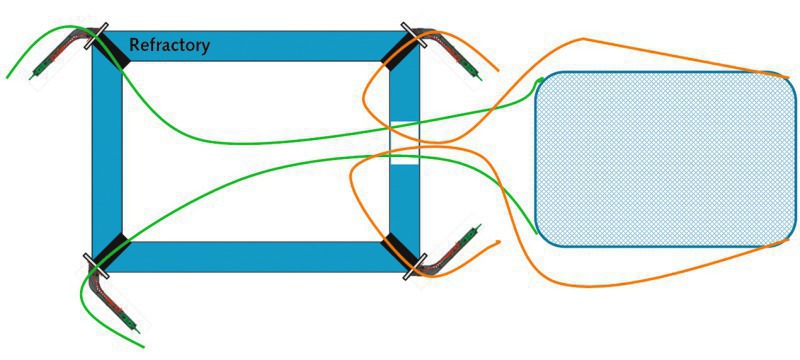
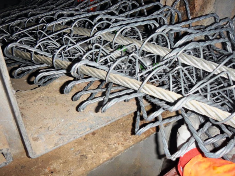
The guiding principle in the development of this solution was that nobody must enter the unsecured riser duct to install the safety nets. In the developed solution, auxiliary rope aids consisting of man-made materials are inserted into the riser duct from outside via the four flange openings and the ends attached outside to the brake units. These four ropes are passed to the outside via the hatch using a boathook, and then tied to the border rope of the safety net (Figure 3). The net is then folded flat in front of the hatch in such a way that the four corners remain facing upward. This “bundled” net is then both pushed and pulled through the hatch into the riser duct using the ropes, with manual assistance (Figure 4). The safety net now hanging in the shaft is then drawn taut using the ropes, until the tensioning ropes can be secured with securing pins using the thimbles in the brake unit. Two experienced employees can install such a net in one hour.
Small pieces of encrustation dropping into the net are resiliently caught and remain on it. If a large piece of encrustation falls, the net initially “gives” resiliently, until the brakes engage. During this process, plastic deformation of the steel bars occurs, absorbing the kinetic energy of the falling material.
Several such rectangular nets are now in use for kiln repairs. A solution for round shaft cross-sections has also been developed and will come into use during the remaining months of this year.
//www.dyckerhoff.com" target="_blank" >www.dyckerhoff.com:www.dyckerhoff.com
Überschrift Bezahlschranke (EN)
tab ZKG KOMBI EN
This is a trial offer for programming testing only. It does not entitle you to a valid subscription and is intended purely for testing purposes. Please do not follow this process.
This is a trial offer for programming testing only. It does not entitle you to a valid subscription and is intended purely for testing purposes. Please do not follow this process.
tab ZKG KOMBI Study test
This is a trial offer for programming testing only. It does not entitle you to a valid subscription and is intended purely for testing purposes. Please do not follow this process.
This is a trial offer for programming testing only. It does not entitle you to a valid subscription and is intended purely for testing purposes. Please do not follow this process.