Numerical simulation of temperature field distribution in the kiln inlet system of a precalcining kiln


For the purposes of obtaining a high-performance clinker while reducing the requisite energy consumption, this paper investigates the temperature field distribution in a precalcining kiln and factors which affect such a temperature field distribution. Based on the solid material balance calculation of four-level precalcining kiln systems, the solid material balance and distribution of the Five Level Preheater + Calciner process (FLPC) were established. Then, the heat balance calcination model was established. The results of numerical simulation of the precalcining kiln were found to closely reflect the actual situation. The separation efficiency of the cyclone, the ratio of calciner coal feed, the temperature of the tertiary air and the surface heat loss all affect the temperature field distribution in the kiln inlet system of a precalcining kiln.
1 Introduction
A precalcining kiln is a series of equipment items for producing cement clinkers. The raw material for cement production is a mixture of predetermined proportions of limestone, silica and small quantities of alumina and iron oxide. The raw material passes sequentially through a preheater, a calciner, a kiln and a cooler to produce cement clinkers. In the preheater section, the raw material is preheated to calcination temperature via heat exchange with hot gases from the calciner. In the calciner, most of the raw material is calcined. The energy required for an endothermic...
1 Introduction
A precalcining kiln is a series of equipment items for producing cement clinkers. The raw material for cement production is a mixture of predetermined proportions of limestone, silica and small quantities of alumina and iron oxide. The raw material passes sequentially through a preheater, a calciner, a kiln and a cooler to produce cement clinkers. In the preheater section, the raw material is preheated to calcination temperature via heat exchange with hot gases from the calciner. In the calciner, most of the raw material is calcined. The energy required for an endothermic decomposition reaction is provided by combusting a suitable fuel. The calciner is supplied with tertiary air from the cooler and with air from the kiln exhaust. The former is intended to supply sufficient O2 for fuel combustion, and the latter serves to utilize the heat content of the kiln gases to enhance the decomposition reaction. There were more than 1800 NSP lines in China in 2016. Precalcining kiln technology has been the mainstream for cement clinker calcination over the past few decades. However, the residual decomposition reaction of calcium carbonate and the slowly rising temperature of material in a rotary kiln are still impediments that impose limits on the kiln’s productivity and energy conservation potential [1]. That is to say, the rate of heat transfer and the need for clinker calcination in a rotary kiln are very much out of balance [2].
According to previous research [3-5], if the temperature of the raw material in the kiln inlet is raised from 900° C to 1000~1200° C , both solid-phase and liquid-phase reaction rates would be significantly accelerated. In other words, the above process of enhancing clinker calcination takes advantage of the high efficiency of heat transfer in a suspension state, which significantly helps to increase clinker production.
To obtain high-performance clinker and reduce energy consumption, it is necessary to maintain a stable physical-chemical process and temperature field. It is therefore important to predict the temperature distribution in the precalcining kiln by way of numerical simulation. To further improve the performance of the precalcining kiln, it is necessary to obtain the effect rule of operation parameters on the temperature field distribution in the clinker calcination system.
References [6-9] established the material balance of a kiln inlet system, but they did not consider the association of material balance of each cyclone preheater and calciner. Reference [10] studied the material balance calculation of a four-level preheater + calciner system, including consideration of the association of each cyclone preheater and calciner. On that same basis, this paper further establishes the mass and heat balances of the FLPC system, as well as the mass and temperature distributions within said system.
2 Computational models and solution
methodology
2.1 Solid-phase mass balance of kiln inlet system
2.1.1 The solid-phase mass balance model of the kiln inlet system
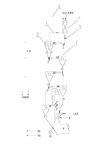
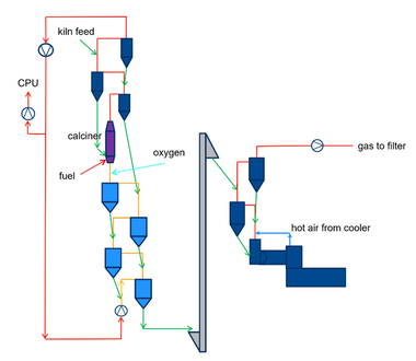
The solid material flow of the FLPC process is shown in Figure 1. The benchmark for calculation was kg/(kg∙cl) clinker. The collected quantity of kiln dust was mainly dependent on the dust collector efficiency of each cyclone, especially the I-level cyclone. When the material consumption was calculated, this part had to be deducted from B0 (raw material entering precalcining kiln system). So, this part was not listed in the solid material balance.
In Figure 1, ηi represents the separation efficiency of each level cyclone. Ai represents the inlet material of each level cyclone. Bi represents the outlet material of each level cyclone. B0 represents the raw material entering the precalcining kiln system, the loss on ignition of which was I0%. fi represents the kiln ash quantity of each level cyclone. G1 represents the fuel consumption at the kiln head, the ash content of which was A1%. G2 represents the fuel consumption of the calciner, the ash content of which was A2%. y represents the kiln ash quantity at the kiln tail, the loss on ignition of which was Iy%.
For the sake of simplified calculation, the following assumptions were made:
(a) The separation efficiency of each level cyclone was assumed as constant
(b) The decomposition reaction of the raw material in the I-, II- and III-level cyclones was ignored
(c) The fuel being fed into the calciner burned out before entering the V-level cyclone
(d) The decomposition reaction rate of the raw material in the V-level cyclone was assumed as constant
As seen in Figure 1, the model of solid material balance of each section was established as follows:
I-Level Cyclone⇥(1)
⇥
⇥(2)
II-Level Cyclone ⇥(3)
⇥(4)
III-Level Cyclone ⇥(5)
⇥
⇥(6)
IV-Level Cyclone ⇥(7)
⇥(8)
Calciner ⇥(9)
V-Level Cyclone ⇥(10)
⇥
⇥(11)
Rotary kiln ⇥(12)
2.1.2 Physical quantity calculation of each section
(1) Material quantity of each section
The following equations were derived in keeping with reference [10]. According to equation (12), the outlet material of the V-level cyclone was listed as shown below.
⇥(13)
So,
Then, the outlet material of the IV-level cyclone was listed as:
⇥ (14)
And then,⇥ (15)
where,
and represent the section provided
by and , respectively.
Whereas, K4 coefficient was assumed,
⇥(16)
Hence, the ignition loss of B4:
⇥(17)
The heuristic calculation method was applied for B0. First, the B0 value was assumed. Then, the values of K4, I4, B4 … were obtained, until a new B0 value was acquired. If the new one disagreed with the assumed one, the calculation was repeated until both were in agreement. After the values of B4, B0, f5 were obtained, the quantities of inlet material, outlet material and kiln ash were calculated according to the above material balance arithmetic expression.
(2) Ignition loss and apparent decomposition rate of outlet material from each cyclone
To obtain the loss on ignition of outlet material from other level cyclones, the ratio of f5 and B0 to B3, B2, B1, respectively, had to be calculated first.
If⇥ (18)
then,⇥ (19)
If⇥ (20)
then,⇥ (21)
If⇥ (22)
then,⇥ (23)
where the coefficients K3, K2 and K1 were assumed as:
⇥ (24)
⇥ (25)
⇥ (26)
Hence, the ignition loss of outlet material from each cyclone was calculated as:
⇥ (27)
and the decomposition rate of outlet material from each cyclone was calculated as:
⇥
⇥ (28)
2.2 Mass and heat balance computational models
2.2.1 Basic assumption
In order to study the precalcining kiln system, we rationally simplify the cement kiln according to the working principles of the cement kiln and the actual parameters of the clinker calcination system.
Some assumptions are summarized as follows [11, 12]:
(1) The physical moisture of the raw material entering the kiln inlet system is ignored
(2) The chemical water of the raw material is completely evaporated in cyclone II
(3) The coal powder is completely burnt in the calciner
(4) The temperature of each unit is uniform. Heat exchange between gas and solid phase is accomplished in each cyclone
(5) The specific heat capacity of the solid material and gas are a one-step fitting correlation on temperature
2.2.2 Balance model
The gas phase and solid material in a cyclone are assumed to be completely back mixed. In Figure 2, Ms is the mass of solids entering or leaving the cyclone. Mg is the mass of the air entering or leaving the cyclone. Mh is the mass of solids entrained by a cyclone.
Thus, for any cyclone in the preheater, the following inlet streams are considered:
(a) Solids from the (i−1)th cyclone (Ms, i−1 at temperature Ti−1)
(b) Solids that are entrained by gas from the (i+1)th cyclone (Mh,i+1 at temperature Ti+1)
(c) Air from the (i+1)th cyclone (Mg,i+1 at temperature Ti+1)
The outlet streams for this cyclone are:
(a) Solids out of cyclone (Ms,i at temperature Ti )
(b) Solids entrained by gas (Mh,i at temperature Ti )
(c) Air out (Mg,i at temperature Ti)
The steady state material balance equation for ith cyclone is expressed as:
⇥(29)
⇥(30)
In the above equations, η represents the particle capture efficiency of the ith cyclone. M represents the mass flow of solids (kg/s), and the subscripts s and h represent solids and entrained solids, respectively, as explained earlier.
The steady state energy balance for the ith cyclone is expressed as
⇥(31)
In the above, Cp,s and Cp,g represent the specific heat of solids and air, respectively. Subscript g represents the air, and Tc,i represents the temperature of solids and air in the ith cyclone. Qloss,i represents the heat losses of the ith cyclone through outer walls. The mathematical model of the calciner is similar.
2.3 Solution methodology
First, the material balance (solid phase and gas) is calculated using relevant known parameters, including for example a typical feed coal ratio (calciner feed coal: kiln head feed coal = 60% : 40%). Then, the material distribution data of each unit are obtained. On this basis, the heat balance equation of each level cyclone cylinder as a heat exchange unit is listed. The heat balance equation of the calciner is set up separately. Thus, six heat balance equations are established. There are six unknowns in the system of equations (outlet gas temperature of each level cyclone and calciner). However, the specific heat c is a function of the temperature T, and the material outlet temperature of each level cyclone and calciner is dictated by the gas-solid temperature difference after the gas-solid heat transfer. Therefore, the system of equations can be transformed into a nonlinear system of equations. For solving the nonlinear system of equations, the numerical method is required [13-15].
The initial value of the simplified linear system of equations is obtained by way of the Gaussian elimination method. Then, the initial value is used in the nonlinear system of equations. Finally, the nonlinear system of equations is solved according to Newton’s iterative method.
3 Basic parameters
Since the mode of heat exchange in the kiln inlet system is complicated, and because a number of parameters are involved, the calculation was simplified by assuming the following parametric values.
3.1 Raw material, clinker and coal powder
The chemical compositions of raw material, clinker and coal ash from the actual production line are listed in Table 1. The industrial analysis and calorific value of coal are shown in Table 2.
3.2 Specific heat capacity
In order to simplify the calculation, the specific heat capacities of the following materials were expressed as a one-step fitting correlation on temperature [16,17]:
Clinker:Ccl = 0.76 + 0.000297t
Raw material: Csl = 0.88 + 0.000293t
Kiln ash: Cfh = 0.822 + 0.0002t
Air: Ckq = 1.011 + 0.000126t
The unit of the above materials was kJ/(kg·°C)
Gas: Cyq = 1.2955 + 4.2456 × 10⁻⁵t
The unit of the above material was kJ/(Nm3·°C)
3.3 Operating parameters
3.3.1 Separation efficiency and surface heat loss
The separation efficiency and surface heat loss of each unit shown in Table 3 were assumed according to practical engineering experience, actual measurements and reference data [18].
3.3.2 Temperature difference
According to practical engineering experience and reference data [16], the temperature difference between gas and solid phase was assumed as shown in Table 4.
3.3.3 Thermal parameters
(a) The temperature of the gas entering the kiln inlet system was 1050°C
(b) The temperature of the tertiary air entering the calciner was 900°C
(c) The temperature of the raw material entering the preheater was 50°C
(d) The leakage air temperature was 50°C
(e) The temperature of the coal powder entering the calciner was 60°C
(f) The raw material moisture content was 0.2%
(g) The mass of kiln ash entering the kiln inlet system was 0.255kg/(kg∙cl)
(h) The amount of coal required for one-kilogram of clinker was 0.135kg
(i) The ratio of calciner feed coal to rotary kiln feed coal was 60 : 40
(k) The ignition loss of the raw material entering the rotary kiln was 5.3% when the ratio of calciner feed coal was 60%
(l) The excess-air coefficients are shown in
Table 5
4 Results and discussion
4.1 Solid material and temperature field distribution in the kiln inlet system of a precalcining kiln
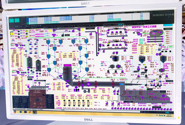
Through the material balance and heat balance calculations, the characteristics of the solid material and the temperature field distribution of the preheater and calciner of the cement precalcining kiln were established as shown in Figure 3.
The screen shot of a precalcining kiln, as described in 3.1, is shown here as Figure 4, which basically represents the actual gas and material temperatures. As illustrated in Figure 4, the results of numerical simulation closely reflect the actual situation. In order to further verify the applicability of these simulation results, they were compared with the engineering test results of the subject precalcining kiln in Table 6.
4.2 Impact factors affecting solid material distribution
4.2.1 Kiln dust
In the FLPC process, the separation efficiency of each level cyclone was a fixed constant. When the amount of kiln dust at the far end of the kiln inlet system increased, B0 remained constant, while the amount of outlet material from the other level cyclones also increased.
Therefore, the change in the amount of outlet kiln dust did not affect B0, but only influenced the solid material distribution in the lower-level cyclones and calciner.
4.2.2 Ignition loss
In the FLPC process, the separation efficiency of each level cyclone was a fixed constant. When the ignition loss of the material entering the rotary kiln decreased, B0, B1 and B2 remained constant, while that of the outlet material from the other level cyclones increased.
Therefore, the change in the ignition loss of material entering the rotary kiln did not affect B0, but only influenced the solid material distribution in the lower-level cyclones and calciner.
4.2.3 Separation efficiency of cyclone
In the FLPC process, when the separation efficiency of the I-level cyclone decreased, B0 increased. And the lower the separation efficiency of the I-level cyclone became, the higher the B0 yield became. However, the B1~B5 yields were always maintained as constants. When the separation efficiency of the II-level cyclone decreased, B0 and B1 increased, while B2~B5 remained unchanged. That is to say, when the separation efficiency of the i-level cyclone decreased, B0~Bi-1 increased, while Bi~B5 remained constant.
The following equation shows that the separation efficiency of each level cyclone had no effect on B5.
⇥(32)
Therefore, the change in the separation efficiency of C1 mainly affected the raw material entering the kiln system (B0). Changes in the separation efficiency of the other level cyclones affected both the solid material balance and the distribution of the higher-level cyclones.
4.3 Impact factors affecting temperature field distribution
4.3.1 Separation efficiency of cyclones
It was shown that changes in the separation efficiency of any cyclone would impact its temperature. The effect of the separation efficiency of that cyclone on the temperature field distribution within the kiln inlet system is shown in Table 10. The exhaust gas temperature of the kiln inlet system rose with any increase in the separation efficiency of the cyclone, because the latter reduced the concentration of kiln dust in the exhaust gas.
4.3.2 The calciner coal feed ratio
The calciner coal feed ratio was a change factor for the temperature field distribution. In order to either increase the decomposition reaction rate of the raw material entering the rotary kiln or to improve the temperature of the tertiary air and secondary air, the calciner coal feed ratio was varied. The temperatures of each unit with different calciner coal feed ratios are shown in Table 11.
As can be seen in Table 11, when the ratio of calciner coal feed increased, the exhaust gas temperature of the kiln inlet system improved. This is due to the fact that the increase in the ratio of calciner coal feed increased the input of heat to the kiln inlet system.
4.3.3 Tertiary air temperature
When the temperature of the gas entering the kiln inlet system was fixed, the temperature of the tertiary air governed the temperature in each cyclone. The temperature of each kiln section is shown in Table 12 as a function of changes in tertiary air temperature.
It was shown that the temperature of kiln each section follows the same trend as the tertiary air temperature. The effect of the tertiary air temperature on the temperature of the cyclone was lower than that of the calciner.
4.3.4 Surface heat loss
As to be expected, the surface heat loss was found to affect the temperature field distribution. When the surface heat loss changed, it affected the temperature field distribution in the kiln inlet system as shown in Table 13.
The results show that the lower the heat loss, the higher the temperature of the kiln inlet system became.
5 Conclusions
According to the relationship between the inlet material, the outlet material and the kiln ash of each level cyclone and the calciner, the solid material balance and distribution of FLPC were established
The temperature field distribution of the precalcining kiln can be solved through numerical simulation. Numerical simulation of the temperature field distribution can give guidance and help to optimize the process operating parameters
Changes in the separation efficiency of the I-level cyclone mainly affected the raw material flow rate entering the kiln system (B0). Changes in the separation efficiency of the other level cyclones affected both the solid material balance and the distribution of the higher-level cyclone. When the separation efficiency of each level cyclone remained unchanged, neither the quantity of the kiln dust leaving the rotary kiln nor the ignition loss of the material entering the rotary kiln had any effect on B0, but merely altered the solid material balance between the lower-level cyclone and the calciner
The separation efficiency of the cyclone, the ratio of calciner coal feed and the calciner affected the temperature field distribution within the kiln inlet system. The kiln exhaust gas temperature rose with any increase in the separation efficiency of the cyclone. The higher the calciner coal feed ratio, the higher the temperature of the cyclone. The temperature of the tertiary air and the surface heat loss also affected the temperature field distribution.
Acknowledgement
This paper is supported by National Key R&D Program of China (Number: 2017YFC0210800), National Plan Project 973 of China (Number: 2009CB623102), Key Fund Project of Sichuan Provincial Department of Education (Number: 14ZA0086), Key Fund Project of the Professional Scientific Research Innovation Team of Southwest University of Science and Technology (Number: 14tdfk01) and Planning Project of Sichuan Province Cyclic Economy Research Center-Key Research Base of Social Science of Sichuan Province (Number: XHJJ-1617).
Überschrift Bezahlschranke (EN)
tab ZKG KOMBI EN
This is a trial offer for programming testing only. It does not entitle you to a valid subscription and is intended purely for testing purposes. Please do not follow this process.
This is a trial offer for programming testing only. It does not entitle you to a valid subscription and is intended purely for testing purposes. Please do not follow this process.
tab ZKG KOMBI Study test
This is a trial offer for programming testing only. It does not entitle you to a valid subscription and is intended purely for testing purposes. Please do not follow this process.
This is a trial offer for programming testing only. It does not entitle you to a valid subscription and is intended purely for testing purposes. Please do not follow this process.